Exhaust
The exhaust has a profound effect on performance, but to get the maximum returns can take a lot of work. There are two basic requirements: firstly we want a system that offers free flow with a minimum of backpressure, and secondly we want tubes dimensioned to provide the best possible scavenging and power output. Before we get to specific sizes, let's take a quick look at how the exhaust works.
Imagine the piston descending on the power stroke. Somewhere after midstroke the exhaust valve begins to open, and the gas, still under a fair bit of pressure, starts to flow. By the time the piston is at BDC the pressure will be mostly relieved, and as the piston rises it shoves more gas out the exhaust port. Clearly we can see that excessive backpressure will incur a horsepower penalty because of pumping losses, but in fact the losses due to pumping are fairly low, even with substantial backpressure. Despite this there is a good reason to limit backpressure: not only does the remaining gas occupy volume that could be filled with fresh mixture, but when the intake valve opens as the piston approaches TDC the backpressure-compressed gas flows back up into the intake port, further contaminating and diluting the fresh mixture.
The real power gains are made through better scavenging. Imagine that the piston has now reached TDC on the exhaust stroke. The gas in the cylinder has been swept out, but we still have a body of exhaust gas occupying the combustion chamber - depending on the compression ratio it could be about 10% or so of the cylinder volume. Unless we can get rid of it the gas will rob space that could be filled by fresh air/fuel mixture, plus it will dilute and contaminate the mixture, slowing combustion. The way we get rid of it is with an efficient exhaust system that uses a mixture of inertia forces from the moving column of gas and sonic activity to literally pull the remaining exhaust gas from the chamber. Of these two forces, the sonic or sound wave action is the strongest. A good illustration of the ability of sound waves to produce power is the two-stroke racing motorcycle engine - these have extremely high specific power outputs that are largely made possible by their expansion chamber exhaust systems.
So how do we make it work? Firstly (and this is a grossly simplified explanation but it'll do for the time being) we use a primary pipe diameter that provides sufficient flow velocity that the momentum of the column of moving gas helps pull the remaining gas from the cylinder as the piston slows down approaching TDC. This is a compromise of course between getting a high flow velocity and keeping the friction losses and therefore the backpressure down. Secondly, we try to make the primary pipe the right length so that as the piston approaches TDC a negative pressure wave is returned from the collector and arrives at the chamber at just the right time to drag the last of the exhaust gases out and get the flow started from the opening intake valve. Of course with an exhaust system of fixed dimensions this can only work well over a fairly narrow RPM range, so it's important to match the exhaust system to the other engine components.
Sound waves are created when the exhaust valve first opens, and a positive pressure wave will travel from the exhaust valve down the primary pipe. Whenever there is a change in cross-sectional area, another sound wave will be reflected from that point back to the source. If the cross-sectional area decreases then the reflected wave will be the same sign or polarity as the original wave ie. if a positive pressure wave hits a reduced pipe area then another positive wave will be reflected back. If however the pipe increases in area, then the wave is reversed in "polarity" and a negative pressure wave will be bounced back to the chamber. This is basically how a typical collected extractor works then: the momentum of the gas column helps pull gas from the cylinder as the piston decelerates. Then the original positive wave produced when the valve first opened will be bounced back from the point where primary pipe meets the collector as a negative pressure wave at just the right time to scavenge the chamber. Providing of course the length is right. It all sounds neat and tidy in theory, but it's not quite so simple in reality. In a real exhaust there will be other changes in cross section besides those at the collector, where other cylinder pipes branch into primary pipes for example. As well, there will be pressure waves from some cylinders setting up waves in pipes from other cylinders and the end result is that there are dozens of waves of different signs and amplitudes rattling back and forth in the system, some beneficial, some not so. Get the dimensions right though, and it all works rather well.
OK, so much for theory, what size pipes do I need for my 202? Well that depends. A tuned system can only work well over a fairly narrow rev range, so for a mild to moderate street car that operates over a wide RPM range I wouldn't even bother with sonic tuning. I'd simply use a set of off-the shelf extractors with the appropriate primary pipe size. In fact, for engines up to about 160hp the factory dual outlet cast manifolds will often perform as well as extractors. The dual manifolds were made for some of the red engines (186S for example) and were standard on all the blue/black engines. Compared to tube extractors they are cheap, quiet, leak-free and long lasting, so don't discount them for the daily hack.
How then do we design a system for a high output engine with a narrow rev range? We need some starting point for the dimensions in order to reduce experimental cut and shut to a minimum. Designing a tuned system can involve enough calculations to fill a book, and indeed there have been several books written on the subject. The easy way - and I love easy ways - is to use software to do the sums for you. Any of the engine simulation programs can do this, plus there are programs specifically for pipe design as well as free online calculators. Interestingly, if you use several of these to design a system for the same engine you'll find they don't all come up with exactly the same dimensions. They will however come up with figures that will be close enough to get you started, and the experimental optimization work will be kept to a minimum should you choose to do it.
OK, here's another very very rough guide: for smaller engines (say less than 179ci) of up to 120 - 130 hp use 1.375" to 1.437" primary pipes. It may be difficult to match your exhaust ports to these small tubes and if so don't stress, just use 1-1/2" pipes. For engines of 130 to about 200 hp use 1.5" tubes. From 200hp to about 275hp 1-5/8" pipes will be about right, and once you go from 275hp to well into the 300's (probably not with a Holden head!) you could probably even make good use of 1-3/4" tubing.
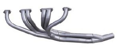 |
| HM Headers HM9C - widely regarded as the best off-the-shelf competition headers |
As for primary pipe length you really need to calculate this for each individual engine as it is influenced by valve timing as well as other factors. Engines at the high end (torque peaks above 6000 -6500rpm) will probably like about 27 - 28", more moderate engines around 30" and streetable engines around 32 - 34", though really you should calculate this yourself or use the appropriate software. Ideally all the primary tubes should be exactly the same length, and most off the shelf extractors will have quite a lot of length variation. Having said that, I'd rather have extractors where at least some of the tubes were roughly the right length than a set where all the tubes were the same incorrect length. The straight six has much more room to fit exhaust manifolding compared to a V8, but even so you may come across primary pipes that dive down at a sharp angle right from the port face. Traditionally it has been recommended to leave a few inches of straightish pipe at the flange before making any sharp bends. Considering what the exhaust gas had to go through to get to the port face I'm not sure whether it's really important - if you have to make a sudden change in direction you might as well get it over and done with while the flow is still turbulent on exiting the port. And remember that the exhaust port in the Holden heads is directed down at a slight angle. Check the port match at the flange and head face, some extractors are way off and will need a bit of work with the die grinder. Some also need help with maintaining alignment with the head. You can sometimes improve the flow on primaries that dive down sharply by grinding a big "short-side" radius on the lower inside edge of the header flange.
To continue our rough and somewhat dodgy guide over at the collector end, you'll probably find good results using a collector with an area of roughly 1.8 to 2.2 times the primary pipe area - the Holden seems to like collectors that are on the smallish side. Thus for 1-1/2" pipes use a 2" collector, for 1-5/8" primaries a 2-1/4" to 2-3/8" collector, and for 1-3/4" pipes a 2-1/2" to 2-3/4" collector. If you have time to spare you may find you can broaden the powerband somewhat by making the collector tapered, ie. make the collector entry area no more than double the primary area, with the outlet area about three times the primary area. To make this work you would need to merge the primaries together gradually (the so-called "merge-collector" design) and this isn't a bad technique to use to merge the primaries together anyway. The collector length isn't as critical as the other dimensions, and if you use a length equal to about 6 or 8 diameters you'll be close. Making the collectors longer often helps build torque at the lower end of the curve.
If you need to run a full system with tailpipe and muffler these need to be as big or a tad bigger than the collector to maintain power. The downside to running such a big system on a street car is that they tend to be "boomey" and the drone quickly becomes annoying. It may be better to run a smaller, quieter system on the street that can be quickly disconnected at the strip. Popular opinion states that pipes bigger than 2-1/4" or 2-1/2" will reduce low rpm torque, but these pipe sizes may be too small for very high output engines which may require anything up to a 3" system. I know from experience that some engines feel stronger down low with a smaller pipe, but I suspect this is an illusion caused by the smaller, quieter pipe. Best performance will come from using a pipe sufficiently big that it appears to the engine to be dumping straight to the atmosphere from the collector. As mentioned earlier though, such a big system may be difficult to accomodate and be annoyingly drummy. A glass-pack style muffler (the longer the better) mounted immediately downstream of the collector can help here; to the engine it appears to be dumping directly from the collector, and it reduces the need to run such a large system after the glass-pack. The other advantage to this setup is that it permits the use of a clearly defined collector length; pipe after the collector can appear to the engine to be simply additional collector length.
Big, baffled mufflers are quieter and sometimes flow as well as or better than the straight-through absorbtion types, even though they are more difficult to accomodate neatly. OEM mufflers from late model injected engines of a similar or (preferably) greater output should perform well, at least as well as the so-called sports designs, and should be cheaply available from the wreckers. Single systems are generally regarded to be best from a performance perspective, though it should be noted that manufacturers such as BMW have fitted dual exhausts to their cars as standard - and if anyone knows high performance straight sixes it's BMW. Their use of dual pipes may be more due to the fact that it's sometimes easier to fit two small pipes rather than one big one though. Regardless, I would stick with a single system unless I had a very good reason to do otherwise.
If there is one piece of advice you should follow it is this: don't just guess the exhaust dimensions or use what worked on your mates engine. Use something like PipeMax to calculate the sizes so you can be confident of being fairly close to the optimum right from the start.