Characteristics and Limitations
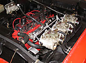
The six is a reasonably light and compact engine compared to an iron V8, and can provide reasonable performance in a lightish car like an early Holden or Torana. Having said that, the red motor wasn't a particularly advanced design even when it was first released and it's ultimately quite limited in output, mainly by the cylinder head design. As we will see later, the cylinder head is the key to making power with the six. The other limiting factor with regard to power production is block durability. While they can handle as much as double the original horsepower without problems, further increases frequently result in a cracked or broken block, particularly when high rpms are used. Blown engines can easily make more power than the engine can reliably withstand - with enough boost power levels of over 600hp are possible if not sustainable. Turbocharging works exceptionally well on these engines; making 400 odd hp is easy, not only that but the power is made at rpm levels below those that cause block problems.
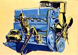 |
| Chev six from the mid 50s. Chev influence on Holdens design is obvious. |
Naturally aspirated, don't expect to get much more than around 220 - 230hp for a streetable engine. This mightn't sound like a lot compared to todays injected V8s, but it's not unusual for a light street car with a hot six to get into the 13s without resorting to nitrous. With exceptionally light cars like the early Toranas 12s are fairly easily achievable but the streetability of such an engine will be marginal. Its possible - if not easy - to get 300+ hp from these engines using radically ported 9 port heads and matching cam profiles, but at these levels the powerband is painfully narrow and the engine will be starting to become fragile. If you really do need much more than say 240hp from a Holden 6, it may prove more practical and cheaper in the long run to use a Jzed/Duggan style head. Not only will you get the peak horsepower, you'll get a wider powerband.
Why - Or Why Not - A Holden Six
I'll be blunt. If performance is the primary consideration and you don't have to use a particular engine to comply with rules then there are much better choices than the old Holden. Modern engines from Nissan or Toyota for example will out perform the old Aussie six by a massive margin - you won't even be in the race. Another older engine with a fair bit more potential - mainly due to it's bigger displacement - is the old Hemi six. All of these engines will outperform the Holden and almost certainly cost less on a horsepower per dollar basis. If however, you don't need to make a million horsepower, or you'll be competing against similar engines, or perhaps you want to build up a cool old-school street car then the Holden six might do the job nicely. Just don't kid yourself that you're going to show these young blokes with their turboed 2JZs a thing or two with the old six - you'll only embarass yourself.
Planning Your Engine
Before for you can start work, it's critical that you have some sort of plan in place in order to be able to choose components that work together and are suitable for the intended use. But before you even start planning you should work out how much power is needed to be competitive, and roughly what sort of rev range will be associated with that power level. If, for example, it turns out that you need 500hp or that the powerband will be only 1500rpm wide then at least you'll know not to waste any more time and money trying to build a winner from a 202 and an Aussie 4 speed...
Some of the things you'll need to address are:
- The anticipated usable rev range of the engine - be realistic and don't be tempted to sacrifice too much power lower in the rev range for big horsepower numbers. By the time you get into the juicy part of the powerband your competition may already have passed you. What you are after is the maximum average horsepower over the usable rev range, with particular emphasis on strength at the lower end of the range. Always remember that to get to the top end you first have to accelerate through the lower speeds. The engine with the most peak horsepower isn't necessarily the fastest one.
- Durability requirements - a street engine that requires monthly rebuilds is obviously useless. Conversely, a conservatively built engine that lasts for 200,000km is unlikely to win many drag races
- Practicality on the street - If it's a street car you're building, don't sacrifice all for peak horsepower. An engine with no usable power under 4000rpm in a street car will be extremely unpleasant. Similarly, engines that require ridiculously high convertor stall speeds will be painful to live with day to day.
- Legal and class rule requirements
- The Budget - This is one area where the final figure is very likely to be much much higher than the original estimate. Spend as much time as necessary on this to come up with a fully detailed costing of the project.
Be particularly careful about determining the usable rev range.
At the top end maximum revs will be largely determined by the
strength of the reciprocating components, and these in turn may be
limited by your budget. The lower end of the rev range will be set
by the available gear ratios and/or the stall speed of the
convertor. You can use this simple formula to work out the rpm drop
at gear changes:
rpm=(gear ratio divided by ratio of previous gear) x maximum
rpm
For example, let's say we have a gearbox where 1st gear is 3.05:1
and 2nd is 2.19:1. Dividing 2.19 by 3.05 gives us 0.718. If we now
multiply our maximum rpm - say 7500 - by this figure we get
5385rpm, the speed the engine will be doing when we change into
second. You can calculate the rev range for each gear like this,
but normally the biggest drop in revs will be in the lowest gears.
In our example, we would want to build our engine to make the
highest average horsepower possible from 5300 odd rpm to our
maximum of 7500rpm. This of course assumes that we can maintain the
revs in this range in real world driving, and that it's possible to
launch the car from a standing start with this powerband. In
reality, it may be necessary to use a bottom rev limit
significantly lower than the calculated figure to maintain
driveability. Clearly then, an engine designed to run with a close
ratio six speed will be hopeless if coupled to a 3 speed box.. It
might be tempting to use something like a Trimatic with a convertor
the size of a doughnut to keep the revs up; just be aware that very
high stall speeds
sap quite a few horsepower at the top end, horsepower that we
can ill-afford to lose with our little sixes.
Once you've determined what rev range you'll be building for, you can start to select components that are appropriate for this range. It is essential that all the components are correctly sized, eg. if you are building an engine to make power from 2500 to 6000 rpm then the camshaft, porting, carb and manifolding, exhaust and compression ratio will all have to be closely matched to this target.
Useful Planning Tools
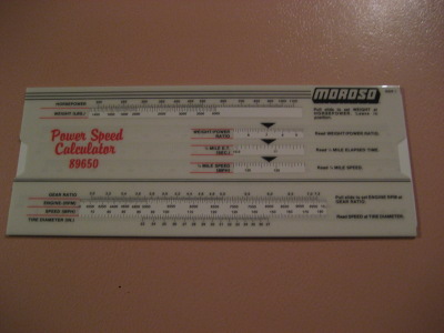 |
| A Moroso Power/Speed Calculator. |
There are a couple of tools you might find useful when planning and designing your engine. The first one, Moroso's Power/Speed calculator is practically indispensable for drag racing projects. For a given car weight and horsepower, it will show what E.T. and terminal speed can be reasonably expected. Or alternatively - and more useful for our purposes - it can show what horsepower will be required to propel our car to a nominated ET or speed. As well as this it has other functions for calculating compression ratios, gear ratios etc. A very highly recommended tool, and cheap too.
Engine simulation software is also useful for planning and designing your engine. Maybe not as essential (or cheap) as the Moroso slide rule but handy nonetheless. While there is a multitude of software packages ranging from the cheap'n'simple to the incredibly detailed (and expensive) there are two programs in particular I'd recommend for the non-professional builder. These are Engine Analyzer (and it's slightly more detailed sibling Engine Analyzer Pro) and PipeMax. Both these will help enormously in the selection and sizing of components. The predicted horsepower figures mightn't be 100% accurate but generally they are very close. Especially good for experimenting with different intake and exhaust dimensions, cam specs, carburetion etc. They can also do all the sums for you regarding calculating static and dynamic compression ratios, fuel rates, timing and many other parameters. Actually the cost of the software is minimal in comparison with the cost of building an engine, and the money is likely to be recouped many times over through the reduction of real-world trial-and-error parts testing. Again, very highly recommended to have before any actual work is started. One of the nice things about both the programs mentioned is that if (like me) you're a Linux user both will run nicely under Wine. See the links section for their web addresses.
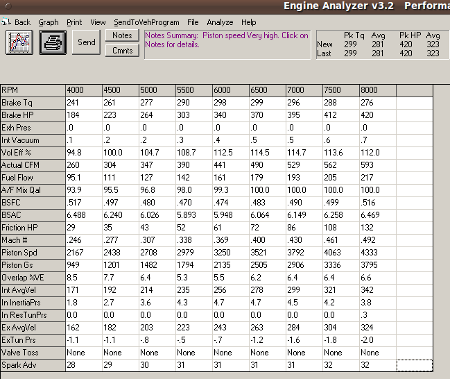 |
| Screenshot of Engine Analyzers' performance calculation window showing the fairly comprehensive output. |
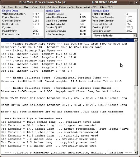 |
| Screenshot of PipeMax showing a small portion of the available output data. |
Choosing The Displacement
If the engine is going into a registered street car, this decision may be already made for you. There are generally restrictions on displacement before engineers approval is required, and this usually means other modifications to brakes and steering for example will also be needed. Also keep in mind that later engines in registered cars usually need to have all the emission controls fitted and working.
Theoretically, maximum horsepower is basically determined by the flow capacity of the engine components, so there shouldn't be a big difference in output between say a 186 and a 202, though the smaller engine will produce its peak power at a higher speed. In practice though, friction losses will be more severe with a smaller, higher revving engine, and the bigger engine will have more area under its torque curve. The bottom line is this: use the biggest capacity you can - the peak horsepower mightn't be much higher than that of a smaller engine but the actual in-car performance will be significantly better.
Whatever capacity you choose, you should run the largest possible bore size (ie. 186/202) in order to minimise the chamber overhang problem that we'll touch on later. There is another advantage to the 202, and that is the availability of a relatively cheap performance piston/ring/pin package in the ACL Race Series parts.
Don't overlook the EFI 202 from the VK Commodore for something to transplant into a daily driver - these are as cheap as dirt and are very close in output to the XU1 - but more civilised.
Stroker motors are fairly popular, and can provide about 235cu in in the most common configuration. Usually they are based on the 221 Ford crank. The original Ford flywheel flange is cut off and the journal turned down. Then the rear journal and flange is cut off a Holden crank and a hole bored into the journal so it can be pressed onto the turned-down Ford rear journal and welded on. The other journals are then ground to suit the Holden rod and main bearings. Provided it's done properly it's quite durable. If you don't like the idea of a welded steel crank new cast units are also available in semi or fully finished form. Slightly modified stock length rods can be used, usually with Ford 250 pistons though others eg. Suburu can be used. A fair bit of work has to be done to make room for the longer crank throw; notches have to be ground into the sides of the crankcase, and the sump needs a bit of hammer work as well. Also the cylinder bottoms need to be relieved a little and the camshaft needs to have some flats ground into it for big-end clearance. Is it worth the extra expense and effort for about 15% more capacity? The extra cubes would certainly improve the performance at lower speeds, and the little Holden has always had a capacity handicap when compared with similar straight sixes from Ford and Chrysler. I tend to steer clear of oddball parts whenever possible, and a stroker crank would add a fair bit of expense. On top of this the rod ratio ends up being awful if you use stock rods and the camshaft relieving weakens it to the point that breakage is likely. But if the maximum possible torque from a low-revving naturally aspirated engine was the goal, I'd certainly consider it.
As it turns out, the maximum practical capacity for a highly tuned engine is not much more than 202 cubes. The lack of big-end to camshaft clearance prevents increasing the stroke by much, and reducing the crankpin diameter would only exacerbate the crank flex. Similarly, it's not practical to increase the bore size, even with sleeving. The existing cylinder walls are already borderline too-thin, and the close bore-spacing means that significant bore increases would leave very little head-gasket support between the bores as well as very little room between the outer walls. In short, we're stuck with the small capacity and therefore must concentrate on making the engine live at the very high revs required to make good power.
Twelve Port or Nine Port?
We'll look at cylinder heads more closely later, but generally speaking it's difficult to get much more than 230 - 240hp from the twelve port heads, while the old nine port heads can be made to flow enough to make over 300hp. Despite this the twelve port head is often the best choice, especially for a street driven car, and at power levels within its limitations a 12 port with the right manifolding will outperform the 9 port because of its fatter torque curve.
Which Block?
Again, if it's for a registered car you may not have much choice. A track-only car can make use of a late blue or black block, complete with counterweighted crank and better rods. But if you want to avoid having to use emission controls you'll probably be stuck with an older (HJ or earlier) red block. These can be fitted with the counterweighted cranks with a bit of work, and it's also fairly easy to adapt the later 12 port heads to these blocks. There is nothing special about the old HP blocks, and while the XU1 blocks allegedly are beefier good luck in finding a block or the money to buy one.
Keep in mind that some of these blocks are over 35 years old, and most have been rebored a couple of times. They are also likely to have a fair bit of corrosion in the water jackets, so you might have to check out quite a few before you find a good one. Pull out the water pump and knock out some of the welch plugs so you can get a good look in there. Finding a good 202 or 186 will be the hardest, many of these will already be bored too far to be used for high performance applications.
Cylinder wall thickness is an important consideration with these engines. For very high power levels bore wall stiffness can be marginal, so you need to find a block that will clean up with the smallest possible overbore - certainly no more than 40 thou if you plan to make much power. A standard or very mild street engine could go 60 thou. over if necessary but generally keep the walls as thick as possible - thin walls are risky with high outputs and even if the engine doesn't fail outright the lack of bore stiffness will cost you power.
If you are building a 3" stroke motor (186/192) keep an eye out for 179 blocks, or even better, the less ancient 173. These engines are cored the same as the 186/202 blocks. This means they can be bored out to 192 specs, but you could start off with the std 186 bore size and have stiffer cylinder walls plus room for a couple of rebores. A blue 173 engine is probably the ideal starting point for a high performance project - not only do you get the good rods and thicker cylinder walls, it also uses 202-size main journals. (Note - there is presently some uncertainty over which blocks can be safely bored to the 186/202 size. Verify wall thickness yourself before committing too much time or money in any block).
Should you choose a red, blue or black block? The later blocks had some minor additional webbing and so may be stronger, and as just mentioned the blue 173 has a lot to recommend it, but on the other hand there is a fair bit of anecdotal evidence to suggest the earlier blocks may be cast from better material. I haven't yet hardness tested any blocks, but it does seem that the old red blocks went longer between rebores. Until I had conclusive evidence though, I'd just use whatever is suitable and available.
Block Prep
For engines of not too much more than 200hp there is nothing special required, unless of course you plan on using a different type of crank. The age of these blocks dictate that you should give any block a good clean and check it out thoroughly for cracks or any other damage before you invest any time or money in it. Line boring isn't usually required, though cutting material from the deck might be be needed to get the squish/quench clearance down - more on this later. Keep an eye out for cracking around the head bolt holes which is quite common, though minor cracks here don't seem to cause any problems. These holes also tend to strip threads so consider fitting inserts and/or studs while you're at it. A honing plate must be used for the final honing operation to ensure the bores are round when the head is fitted. Bore finish is quite important, and should match the rings requirements. Generally a 280 grit stone will be best for chrome rings and a 400 grit for moly or moly-plasma faced rings. It's generally accepted that an automatic machine can give a better, more consistent result than hand honing.
We touched on the importance of maintaining the maximum possible cylinder wall thickness earlier; trouble is it's getting hard to find blocks that haven't already been rebored several times, and anyway you could argue that a very high HP engine would benefit from walls stiffer than those in a virgin block. This can be achieved through sleeving with high-strength thinwall sleeves. The success of such an operation though rests almost entirely on the person doing the machining. If the job is done properly, a sleeved engine will make more power, have more strength and last longer than a normal unsleeved block. If the machining isn't 100% though, it will fail quickly and this is probably why sleeved blocks have a poor reputation with some. The sleeve and block must be machined to very close tolerances, and the sleeve must press up against a step or shoulder to ensure a reliable seal with the head gasket. It's not practical to use sleeving as a means to enlarge the bore; in order to maintain a reasonable thickness of material around the sleeve and in the sleeve itself you'll probably end up with a bore no bigger than standard and possibly a bit smaller. The improvement in wall stiffness will more than compensate for the smaller capacity, especially with very highly tuned engines. Sleeving a high revving high output engine is a different matter altogether to sleeving something like a worn out tractor engine - you might have to talk to several engine machinists before you find one with the experience and competence to do it correctly. Properly done though, there are definite strength and performance benefits to be had.
Blocks for Continuous High Horsepower Applications
The little Holden seems to be able to handle much higher power levels for shorts bursts quite well, and indeed there are some very high powered blown drag race engines around. But if you run the engine for prolonged periods at horsepower levels over the high 200s you will probably find the block will be quite susceptible to cracking and splitting, and while there are some things you can do to help there are definite limits to how much power can be made reliably. Pushed hard, they will split horizontally right down the left hand side, the crack intersecting the welch plug holes. Very high rpms seem to be the main cause of the breakages, though builders of blown motors in may also have to choose between higher boost levels and block durability.
The breakages seem to be more a result of vibrations and forces transferred through the block from the crank rather than simple overstressing. It's therefore more productive to focus attention on the preparation and balancing of the rotating assembly than to try to strengthen the block itself - see the sections on the crankshaft and balancing for more detail.
Running a steel girdle on the mains might help to some degree, though there seems to be remarkably few problems with main caps walking or breaking, the main benefit of a heavy rigid girdle is as a vibration dampener. Grout filling the block will also help dampen the harmonics to a degree, and also provide a little more cylinder wall stiffness. The amount of grout fill will of course will be a compromise between stiffness and cooling, particularly for engines running petrol rather than methanol. The top 30mm - 40mm of the cylinder is the section that is under the most stress, and is therefore the bit that would most benefit from some grout support. Unfortunately this would also preclude any coolant circulation so would only work with a drag engine. You can however run some grout in the lower part of the water jackets without any overheating problems even in a street or circuit car, and it will help stiffen the cylinders a little bit. Filling to the bottom of the water pump opening will result in about 50mm of grout around the base of the cylinders, and while it's not really where the support is most needed it will help a bit.
In an attempt to strengthen the block, some guys have run long head studs that run through the deck and are anchored into holes tapped into the block at the bottom of the cylinders, and this will certainly help tie things together. It's not practical to do this on the cam side as the outer block wall prevents a straight shot from the deck to the base, but on the welch plug side where the support is needed most it's fairly easy to do. Unfortunately the block is quite thin at the base of the cylinders so drilling and tapping will probably weaken this area seriously - and remember this is also where the main webs are anchored. You may be tempted to run long studs all the way from the main caps to the head, but even if you somehow get past the cam-side wall the studs will then intersect the oil passages and you'll be removing material from an area that can ill afford it. Not only that, you'll have to somehow seal around the studs to prevent coolant leakage into the sump and also at the head end. It mightn't be impossible, but I seriously doubt it would be worth the effort and the end result could well be a block that is weaker than it was originally.
The later blocks have a little more webbing than the early red blocks so should be a bit stronger, but prolonged high power levels will be problematic for any block. Drag or street engines should have few problems but for applications such as circuit racing it's something to consider. The way to help the block survive is not by working on the block itself, but by using the lightest possible pistons and rods with a properly balanced counterweighted crankshaft. More details in the relevant section. For engines that are less than very highly tuned - and any remotely sensible street engine - block breakage is unlikely to be much of a problem, even with a non-counterweighted crank.
The Crank
There are quite a few different types of cranks for the little Holden. There are two stroke lengths; the 202 engine uses a 3.25" stroke while everything else from the 138 red up to the 186 is 3" stroke. There are also two different materials used; the 3" cranks made before the introduction of the HK in mid '67 are steel, plus the 186 X2, the 186S and the 186 XU1s used steel as well, while all 173s and 202s are cast. Strength and durability doesn't seem to be an issue for either type, and remember Brocky won Bathurst in a cast cranked 202 Torana so I wouldn't be too concerned about the lack of steel 202 cranks. Big end journal size is the same with all engines, but the 202 and the later (blue) 173's use a bigger main journal than the others.
The later 12 port 202 (but not the 173) engines had fully counterweighted cranks that make life quite a bit easier for the mains and the block. For a street motor or any engine that is subject to sustained high revs I'd go for the counterweighted crank, though for some forms of short-duration racing the lighter non-counterweighted crank might have an advantage. See the section on balancing for more details on this. Besides the different main journal diameters mentioned earlier there are also variations in rear main seal dimensions so if you are planning to use a 202 crank in an earlier block (perhaps to make an engine that's bigger than the numbers on the block indicate) you will have some machining to do. The rope seal cranks have a slightly bigger diameter seal journal than the lip seal cranks, but the journal can be ground down to the smaller size if necessary. This allows a late fully-counterbalanced 202 crank to be used in a red neoprene-seal block. The neoprene seals seem a bit more prone to leaking than the rope seals but either will work if installed very carefully. Installing a 3-1/4" stroke crank in a 3" block requires the main tunnels to be line bored or alternatively the cranks can have their main journals turned down, apparently with no ill effects. Bearing clearances should be no more than .0025" to .003", which might be considered a little bit on the tight side for hi-performance engines. Similarly, you want to keep the rod side clearance fairly close to the stock figures in order to prevent throwing too much oil around. When scrounging for cranks keep an eye out for units that were used with an auto transmission - the manuals had a tendency to wear out the thrust faces fairly badly.
Drilling and tapping the crank snout is worth considering; not only does it enable the use of a balancer retaining bolt it also lets you pull the balancer onto the crank gently instead of driving it on with a hammer. Don't make the thread so big it weakens the snout - 3/8" UNF is enough.
Some of the earlier cranks had smaller diameter oil holes, and while these cranks were fine for normal use they were prone to bearing problems at high speeds. Later 202s etc. were drilled 15/64" and this is sufficient for competition use. Definitely do not crossdrill the journals. It's normal practice to slightly chamfer any sharp edges or corners on the oil holes but don't get carried away and flare them too much - it just reduces the bearing area.
Some people like to run knife-edged cranks, where the outer circumference of the counterweights are bevelled back to an edge. Sometimes the leading edges of the counterweights are bevelled too. The idea is to reduce the windage and drag on the crank, and it also reduces the rotating mass. While this sounds cool I'm not sure it's worth it on a horsepower-per-dollar basis. I know that the oil wrap-around effect on the crank can cause drag and sap power at high revs, but unless you plan on going the whole hog with a special sump design and scrapers and so on I suspect the gains from running a knife edged crank on its own would be minimal. There's another even better reason to avoid knife-edging: it will be impossible to balance the crank to a 50% balance factor with so much material removed from the counterweights and this makes the knife-edged cranks unsuitable for any high rpm work where block and crank durability is important.
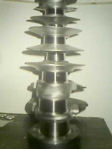 |
| A knife edged crank. Don't do this unless you can afford to compensate for the reduced counterweight with lots of Mallory metal. |
You could probably get away with using a new standard balancer on a 3" stroke engine or a mild 202, but for high RPM work you'll have to use a competition style balancer as an absolute minimum, especially on a 3.25" crank. If you decide to use a stock balancer consider fitting some sort of retaining ring or flange to the front to stop the rim from walking off the hub. There are a few different types of heavy duty balancers around and while they aren't cheap they can be good insurance. A stock balancer may come apart at high speeds, with possibly disastrous results. Depending on what combination of balancer and timing cover you are using, the timing marks may not actually indicate TDC so remember to check it and re-mark it if necessary. More info in the next section..
Managing Torsional Vibrations
At high rpms, the Holden crank suffers from a fair bit of torsional vibration of the crankshaft, though it's not as severe as in some other straight sixes. For those not familiar with the phenomenon a quick summary goes like this: the crank is being continually subjected to impulsive forces from combustion and compression pressures as well as inertial loadings from accelerating and deccelerating the reciprocating bits. These forces vary in direction and magnitude and tend to make the crank motion somewhat jerky rather than spinning at a constant speed. Now, the crank isn't perfectly rigid and is somewhat restrained at one end by the flywheel and the load but is relatively free at the front. Because of this there is some relative twisting forward and back between the ends of the crank. Providing this isn't excessive it's not a problem (say not much more than a degree or so). The thing is though the crank (because of its springiness) has its own natural resonance or frequency that it wants to vibrate at, a bit like a guitar string. And if the frequency of the impulses fed into the crank match the natural resonating frequency of the crank (or a multiple thereof) then things can get ugly. If left uncontrolled the amplitude of the torsional vibrations will jump dramatically. This isn't just a gentle buzz either, the vibrations can be violent enough to break the crank, or shear the flywheel bolts or shake the rim off the balancer. Incidentally, it's quite common for straight six crankshafts to resonate at a frequency that corresponds with 6000 - 6500 rpm. Provided you can stay above or below these critical speeds then vibration is usually negligible or at least manageable. Controlling the vibrations is a separate story...
I've recently spent a fair bit of time studying published information regarding torsional vibration and different types of harmonic balancers. The idea was to gain an understanding that would help me select a suitable harmonic balancer for a somewhat oddball Holden six. Unfortunately after many hours of research I'm really no further ahead; while the physics of torsional vibration are well understood, there is little in the way of reliable data related to the hardware needed to control it. Manufacturers data often seems to be deliberately incomplete or misleading, and much of the information related to practical control of TV is contradictory. For what it's worth (and it's not worth much) here are a few notes on different styles of dampers:
Rubber bonded dampers (like the OEM style) are by far the most popular. They consist of a heavy outer ring attached to a crank mounted hub by a thin layer of rubber. They have a natural resonant frequency that depends on the mass of the ring and the characteristics of the rubber. Manufacturers claim that they are carefully tuned to match the particular engine but this is not strictly accurate. All that's really important is that the resonance of the balancer doesn't match the resonance of the crank. Detractors claim bonded balancers are only effective at a certain rev range but in reality they are fairly effective over a wide range of speeds - excluding of course the speed that matches the balancers own resonating frequency. Manufacturers publish graphs showing that these types outperform other styles and as far as I'm aware these are the only type of balancer available off-the-shelf for the little Holden.
Fluid damped units (eg. Fluidampr) again use a heavy ring, but this time it's in a closely fitting steel shell that holds a heavy viscous silicone fluid along with the ring. Viscous shear provides the damping action. These units have no natural resonance of their own so I guess they would eliminate the possibility of inadvertantly operating them in the "wrong" speed range. They seem to be mildly effective over the entire range but perhaps less effective than the other types at very high frequencies. Commonly fitted as OEM on low speed/high amplitude applications such as large diesels where they seem to perform exceptionally well. Again, manufacturers publish graphs showing their product outperforming the other types.
Pendulum type balancers have been used extensively on aircraft engines for years, and an automotive unit using roughly the same priciple is available in the TCI Rattler. This design uses a solid wheel which has had several (usually nine) holes drilled through, close to the periphery. Steel rollers fit into each hole with a certain amount of clearance and as the crank vibrates the rollers are displaced within the holes to a different position. The mass of the rollers looks quite small compared to the pendulums in the aircraft engines though having said that the Rattler does seem to enjoy a fairly good reputation. There is no natural resonance with these balancers and they are said to be effective over the entire range. TCI publishes graphs showing (surprise, surprise) the Rattler outperforming the other types.
 |
| Pointless picture of TCIs "Rattler". You can't see the rollers in this shot but just look at that cool rattlesnake! |
If you plan on frequently running high revs - say 6000rpm plus - then it's important to get a suitable balancer on the front of the crank, and this will very likely be bigger and heavier than the stocker. Romac make some fairly big competition balancers for the six - as to their effectiveness I don't know for certain. Fluid filled dampers from Perkins diesels have been used very successfully in the past though I doubt if the original designers of these ever intended them to see very high speeds. Another alternative is to adapt steel competition dampers made for larger engines, eg. Chev V8s. The damper rim/rubber ring combination on these style units is supposedly tuned to suit specific applications, but the important thing I think is getting a unit with sufficient mass. And you could probably argue that a Holden 6 at 8000rpm would be producing torsional vibrations at a similar frequency to a Chev V8 at 6000rpm anyway. Adapting a fluid or pendulum type balancer from another engine would sidestep the potential tuning problem and may be a safer option. Finding the space to accomodate a big balancer might not be easy, but if you're turning big revs then you really have no choice.
A steel flywheel is also a necessity if you'll be running higher rpms, say 6000 plus. You might get away with the cast wheel but for the price of a steel one it's just not worth the risk. Flywheel weight is a matter of personal preference and is also subject to the intended usage. Cars with a very high power to weight ratio will benefit from the lightest possible flywheel, while at the other end of the scale it could pay to use plenty of flywheel weight with a heavy, modestly powered car. Full bodied sedans built for drags that aren't traction-limited (and that would be most n/a sixes) will usually run quicker with a lot of flywheel mass. The heavy wheel will help get the car off the line and may more than make up for the slight drop in acceleration. Torsional vibration also manifests itself at the flywheel end, most commonly by continually loosening the flywheel bolts. The later engines used a dowel to help stop the flywheel from walking on the crank flange. As a minimum on a competition engine you should use two hardened dowels and a set of ARP style bolts. The mating faces must be perfectly clean, flat and dry before assembly.
Rods
For a mild street engine, particularly a 3" stroke that won't be revved much past 5000rpm the stock red motor rods should be fine. In an engine that won't see much more than say 6500 - 7000rpm use the heavy duty rods from either the 4 cyl Starfire engine or the later blue/black engines - they are the same rod and use a slightly larger bolt than the red rods - 11/32" versus 5/16". However if you're going to be turning 7000 - 7500rpm plus then it would be wise to use something stronger. In the past it was fairly common to use rods from other makers, eg. rods from Mini, BMW, VW Passat and Toyota engines have all been used, but considering the reasonable price of some of the aftermarket rods it would probably be better to take this route instead. Aluminium rods would normally be a good choice for an engine like the little six, for their light weight as well as their shock-dampening capacity, but the close proximity of the camshaft to the crank makes fitting the bulky aluminium rods difficult.
Always replace the rod bolts when stripping and reassembling the engine, the aftermarket ARP bolts are the usual choice.
Aftermarket rods give us the option of using a longer rod for a better rod:stroke ratio so we might as well take a quick look at this. A longer rod is desirable at high rpms; it makes for slower piston velocities to and from TDC (with a corresponding increase around BDC) and this gives slightly higher average combustion pressures as well as less side loading on the Holdens slightly fragile cylinder walls. The stock rod ratio is barely reasonable on the 3" stroke engines; on the 202s though it's definitely on the short side and it's certainly worth looking at for higher rpm work. Before you go ordering special rods though there are some practical considerations to think about. Firstly the increase in rod length has to be quite large to have any appreciable effect - it's unlikely that a rod of only 5mm or so extra length would make measurably more power, though another 15 - 20mm or so would help. But this leads us to another problem, the piston. Obviously a longer rod will require a piston with a higher pin position, but there are limits to how far this can be taken. The side load from the rod angularity is transmitted to the cylinder wall via the gudgeon pin and piston skirt, and ideally the pin would be positioned exactly half-way up the skirt to maintain durability and minimise drag and piston rock. Moving the pin centreline towards the piston crown puts side loads on the ring pack, a part of the piston poorly suited for this duty. Piston rock at TDC will increase while ring seal and durability will decrease.
What I'm getting at is this: substantially longer rods will improve performance, but only if a reasonable pin position can be maintained. The deck height of the Holden block allows for using rods of up to about 5.9" long with a 3-1/4" crank and reasonably proportioned pistons. But if using longer rods also meant using ugly pistons I'd just forget about it and stick with rods closer to the stock-length. This pin position issue (along with an excessively short rod ratio) also arises with stroker engines, and again it would pay to do whatever was necessary to keep the pin as close to the middle of the skirt as possible, perhaps by slightly crowding the ring pack towards the crown. In extreme cases a special piston could be made with a single compression ring positioned as high as possible, and with the oil ring below the pin.
Stock rods - including Starfires - use a pressed in gudgeon pin. This seems to work well even with fairly big increases in speeds and horsepower, but in an all-out engine floating pins will be less likely to gall the pin bores of the piston. Starfire rods have had the little end bored for bronze bushes successfully in the past, but the wall thickness will be very thin after this operation and I'd be a bit nervous about doing it. Quality control isn't all that flash with the Holden rods and some of the pin bores end up being quite a bit off centre. If you must bush Starfire rods try to find rods that have a uniform amount of material around the little-end eye.
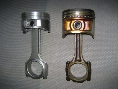
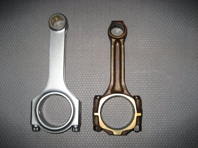 |
| A 5.71" Eagle rod on the left, a stock Starfire on the right. Note how poorly the little-end eye is centred in the Holden rod. |
Balancing
It seems like nearly everyone has an opinion on engine balancing and the ideal balance factor. Search the internet forums for "engine balancing" and you'll soon be wading through thousands of posts. Unfortunately most of them will contain nothing but misinformed opinions, hearsay, old wives tales and plain old BS. Pretty typical misinformation levels for car forums come to think of it. For what they're worth here are my opinions...
Depending on the application, balancing can be either a non-issue or it could be of supreme importance. Mild street engines with a rev ceiling of not much more than say 5000 - 5500rpm will survive quite nicely without any particular attention, and with either a counterbalanced or non-counterbalanced crank. Providing the piston and rod weights are reasonably matched I wouldn't bother with balancing at all. If it makes you feel better though, go ahead and balance it.
As the rev range rises though, it becomes more and more important to both use a counterweighted crank and to have the entire rotating assembly balanced. Once you get into the speed ranges of 6500rpm and above, it becomes critical to use the lightest possible rods and pistons along with a fully counterbalanced crank in order to avoid breaking blocks.
Before we go any further we might just take a look at how the rotating and reciprocating masses act within a multi cylinder inline engine. As usual this'll be a grossly oversimplified explanation but hopefully it will help. Picture a typical inline four (it's simpler than a six but the same principles apply). It will have a single plane crank, where pistons 1 and 4 rise and fall together, as do 2 and 3 which are 180 degrees from the end cylinders. Ignoring the rotating masses for a minute imagine pistons 1 and 4 approaching TDC - by the way the crank on our engine has no counterweights whatsoever. As they are slowed down they pull up on the rods and this force is transmitted through the crank to the block. Now, if there were no counteracting force applied these two pistons would be jerking the engine up and down every time they pass through top or bottom dead centre. Riders of old Triumph and Norton twins will understand this intimately. The thing is though, as 1 and 4 approach TDC pistons 2 and 3 will be slowing as well as they approach the opposite dead centre, providing a countering downward force that exactly cancels out the force from the other two cylinders. Similarly, if we now look at the rotating masses (crankpins, rod big ends etc.) we see that they also balance each other out (being 180 deg apart) without needing any counterweights on the crank at all. The Holden six has a similar inherent balance, and so runs more or less free of vibration even without counterweighting - and even if it does have counterweights the vibration level won't change much regardless of the balance factor used. (In practice, the Holden six can buzz quite badly at high revs. But this is mainly due to torsional vibration of the crankshaft, a different kettle of fish altogether and mainly unrelated to balancing).
Okay then, if vibration isn't a problem why is it so important to run a counterbalanced crank on our sixes? Let's go back to our four cylinder engine for a minute. Imagine the crank is spinning at say 8000rpm, and pistons 1 and 4 are being slowed down as they approach the top of their stroke. Lets say each of these pistons is applying a force equivalent to about 2000kg, and likewise pistons 2 and 3 are each applying the same force downwards. Obviously the forces will cancel each other out and there will be no tendency to vibrate. But look at where the forces are applied. In effect we have a force equivalent to 2 tonnes applied upwards at each end of the block, while another 4 tonnes is applied downwards to the centre. In other words we are expecting the block to act as a beam as we apply pretty severe bending loads to it. Imagine supporting the block at each end and pushing down on the middle with a hydraulic press, then releasing the weight before rolling it over and repeating the procedure. Now imagine doing this 16000 times a minute. Looked at in this way it's pretty easy to see why the Holden blocks tend to disintegrate when subjected to high speeds with a non-counterweighted crank. Remember too that these huge loads make their way to the block through the crank and the bearings, so these too are stressed considerably.
It's pretty obvious that if we fit counterweights to each crank web we can provide a counteracting force for each cylinder that acts on the individual cylinders axis, and thereby eliminating the bending loads on the crank and block. If we use a balance factor of 100% - ie. a counterweight equivalent to all of the rotating mass as well as all of the reciprocating mass - then the loads on the main journals and block can be completely relieved at top and bottom centres. This introduces another problem though. At mid stroke the counterweights will be applying lateral forces at opposing locations to the block, so we still have bending forces at work. The solution is to compromise by using a balance factor of around 50% instead - ie. a counterweight equivalent to all of the rotating mass plus half of the reciprocating mass. This way we reduce the loads at top and bottom centres by about half, while introducing lateral loads at mid stroke that are of a similar magnitude. In other words we swap two big vertical forces for two small vertical forces plus two small lateral forces. This 50% balance factor will provide the smallest possible loading at any given point in the cycle, and should be used by default for most engines. It seems fashionable at the moment to "overbalance" engines for very high rpm work, using balance factors of 60 or more percent. Typically though, the people doing this provide no logical or convincing reasoning for this. I guess if you had reliable data showing that your block is stiffer laterally than vertically, or vice-versa, then you may be able to justify some amount of under or over balance. In the absence of this data though I'd stick with about 50%.
Some builders like to add a few grams for oil, though how the hell they know exactly where the oil will be clinging to the rotating and reciprocating bits is beyond me. Some also painstakingly balance everything to a jillionth of a gram but like the oil thing this is just wank. If the individual components share weights within a few grams, and the balance factor is somewhere near an appropriate figure then it's as good as it's going to get. Taking it to ridiculously fine tolerances will achieve no measurable results.
We briefly looked at knife-edged cranks in the crankshaft section, but it may pay to reiterate here: if engine durability is a factor do not knife-edge the counterweights. It will be impossible to balance one of these cranks to a 50% balance factor. Your engine builder may tell you that he can balance the modified crank perfectly (and he probably can) but it will end up being balanced to something like a 30% factor. For a high revving Holden six that's already somewhat fragile I feel the slight gains from reduced weight and windage are far outweighed by the significantly increased stresses introduced by the cut-down counterweights.
So what do we do if we want or need to rev our engine to the moon (and remain in one piece)? First of all we minimise the forces by using the lightest pistons and rods available/affordable. Then, by using a fully counterbalanced crank we can reduce the abuse the block has to absorb by about 50%. A heavy, rigid main girdle can also help by dampening vibrations and stiffening the block laterally. Builders of smaller, 3" stroke engines are disadvantaged in that counterbalanced cranks aren't available. In the Holden sixes heyday engine builders recognized the importance of counterbalancing and went to the trouble of welding weights to the original steel cranks, though this will obviously be time-consuming and/or expensive. A billet crank is another expensive alternative, otherwise you're pretty much stuck with using a late 202 crank.
Oiling and Oil Pumps
The stock Holden system is simple and relatively trouble free on a stock or mild engine, but could use some help with high rpms and high hp. The Holden, like nearly all engines, has a bit of a problem supplying an appropriate amount of oil over a wide range of speeds. Increases in the crank speed do lead to a slight increase in oil requirements due to the increased throw-off, but its nowhere near the increase in oil flow provided by the pump as revs increase. The net result is less-than-ideal flow and pressure at low speeds but too much at high speeds. Depending on the oil viscosity and the bearing clearances it will take anywhere from 20 to 30 litres per minute to oil the little six. The standard size oil pump can supply this and so should be sufficient for nearly any high performance engine, and the only application I can think of where a high volume pump might be useful is an engine that runs at unusually low speeds and high loads; a turbo engine perhaps. It's surprising how much power is absorbed by an oil pump, and if you've ever primed a Chev with a power drill and dummy distributor you'll have experienced it first hand. Whenever there is an excess capacity the unused oil blows over the relief valve, and the energy that goes into this work is converted into heat. In other words it makes the oil hotter, and this is another reason to avoid the high volume pumps.
It's worth remembering these motors are pretty long in the tooth so you'd want to check out any used pump carefully before using it again. Check the clearance between the tips of the gear teeth and the pump body and reject any pump with more than a few thou clearance. Also check the end clearance and keep it down to about 2 thou. Backlash between the gears isn't really critical but check for badly worn or scored gears, or worn shafts and bushings. If there is any doubt about a used pumps condition it's best to replace it.
Higher speeds and looser bearing clearances - both of which are typical for a high performance engine - will require higher volumes of oil. The standard pump will handle this, but the stock suction too small to ensure an adequate supply. The standard suction line is made from 1/2" steel tube, with an I.D. of about 7/16". If you want to retain the factory suction arrangement (and it's perfectly fine with a factory style sump) it pays to enlarge it a little. There's no need to go overboard, flow capacity is proportional to the square of the tube diameter so even a small increase in tube size will help substantially. A 5/8" tube will work, but remember to also open up the fitting and the drilling in the block that leads to the pump. The stock pickup can be reused with the bigger tube; it may pay to slightly flare the end that is attached to the pickup to ease the entry into the tube, like a little bellmouth. Don't forget to reattach the support brace to prevent the tube from cracking. Your local hydraulics supplier should be able to provide the tubing and fittings.
The other way to upgrade the suction line is to use an external line, and this is the approach commonly used with so-called competition sumps. The original suction line is plugged and a hole drilled in the appropriate spot towards the front of the pump cover plate. A threaded adaptor is silver soldered to the plate and a hose run from this to the sump. Using this method means you can make the suction line as big as you like, but 5/8" to 3/4" I.D. should be plenty for any application. Again, you need to maintain this dimension all the way from the pickup to the pump port. There is really no need to use those gay looking anodised fittings and stainless braided hose - the appropriate stuff from your local hydraulic hose shop is at least as good. It's important to reface the cover plate after attaching the adaptor to address any minor distortion that may have occurred.
A short passage, about 7/16" diameter and a few inches long runs from the oil pump and intersects the main oil gallery just behind the no. 4 main. The main gallery is about 9/16" in diameter and runs the full length of the block. From the main gallery to the mains are 1/4" drillings to oil the main bearings. Mains 1,3,5 and 7 have additional 11/64" holes leading from the mains back to the cam bearings. No. 1 main also has an additional hole that leads to the cam gear nozzle. Opening up the passages to 1,3,5 and 7 is good insurance against the cam bearings bleeding too much oil from these bearings.
The main oil gallery intersects the lifter bores, so check that none of these bores are worn otherwise you'll be bleeding off oil before it gets to the crank. Years ago some builders ran external lines to the end bearings but if you don't run excessively thick oil or excessive bearing clearance, drill the passages to the odd numbered mains and you have sufficient pressure this is unnecessary. I can't stress enough the importance of keeping the viscosity down and also of not loading the engine until the oil has warmed up. I've seen several cranks/bearings that have been burnt simply because the too-thick oil that was used didn't flow quickly enough. On the other hand I've also seen other engines where the oil has been thinned dramatically (through fuel dilution) where the bearings have survived nicely.
Basically all you need to do for the bearings to survive is this:
1, Use a pump suction line of at least 5/8" and open up the passage to the pump
2, Use a die grinder to blend the passages between the pump and block
3, Drill the passage from the pump to the main gallery from 7/16" to 1/2"
4, Drill the passages from the main gallery to the odd numbered mains from 1/4" to 9/32"
5, Shim the relief valve to approx. 65psi.
Naturally all the oilways in the block and crank will have to be thoroughly cleaned, and if you avoid excessively loose bearing clearances you should have no trouble maintaining enough oil pressure. Two to three thou should be enough to ensure a reasonable flow across the bearings, but not so loose as to drop the pressure too much at lower speeds. Most lifters have a 3/32" oil feed hole; if there is too much flow to the top end the hole can be filled with low melting point silver solder and redrilled. This method should be more reliable than the old "pipe cleaners in the pushrods method".
Of course all this work will be for nothing if the oil pump pickup becomes uncovered, even if only for a second. The primary objective of any oiling system will always be to provide a constant, uninterupted flow of oil. Do whatever is necessary to build or buy an oil pan that will suit the intended use of the car. Under full load the bearings can be burnt in a painfully short time without oil - picking up a momentary bubble of air may damage the engine in a time period too short for the oil pressure gauge to react. This is one thing you absolutely must get right.
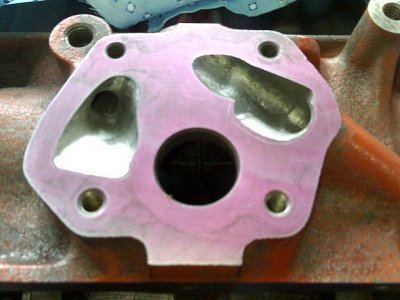 |
| Oilways leading into and out of the pump have been shaped and blended to reduce pressure drop.(photo courtesy Jeff O'Rourke) |
Choose your oil carefully and be aware that nearly all modern petrol engine oils will be unsuitable for a high-output Holden straight six. Unfortunately you can't find out much about an oil just by reading the container - even the SAE viscosity numbers cover such a wide range to be almost useless. An example of this is an oil marketed as say SAE30 that is at the high end of the 30 range. This oil may actually be more viscous than another oil at the low end of the 40 range that's marketed as an SAE40. It pays to check the makers Technical Data Sheets where you will find accurate specs on the viscosity at various temperatures as well as other info. While we're on the subject, viscosities really have little relation to an oils lubrication abilities so there is no point in running a thick oil, the increased drag just robs power. If you can't maintain adequate pressure with a 15w-40 oil you have problems. Years ago monograde oils had a significantly higher load capacity than multigrades but today there is very little difference so definitely go for the multigrade. It's crucial that you be gentle with the engine until it is thoroughly warm - keep the revs and the loading down until then. A 15w-40 will circulate from cold and give sufficient protection when hot. Leave the SAE 50s and 60s to the Harley guys.
For those running a flat tappet cam - and this will be nearly everyone - look for an oil that contains zinc dithiophosphate (ZnDTP). Almost none of the modern petrol engine oils and only some modern diesel oils have it, the reason being modern roller cammed engines don't need it and also because it tends to foul catalytic convertors and oxygen sensors. You mightn't find the ZnDTP level mentioned in the tech data sheets but it will probably be in the Material Safety Data Sheets. More than likely you will end up using an oil designed primarily for diesel engines (eg. Rimula Super) and these generally work very well. Just don't put it in a very high mileage engine that hasn't previously been using diesel oil. The high detergent levels will quickly loosen up the accumulated crud in the engine with unpleasant results. For competition use there are quite a few racing oils (eg. Valvoline) that have high zinc levels, and these are even better than the diesel oils in high rpm applications.
What about synthetics? It's possible to pick up a few horsepower by using synthetic oil but there are a couple of things to watch out for. Firstly, make sure you use a mineral oil to break in the cam and bed the rings, and be 100% certain that the rings are fully bedded in before switching to synthetic. Also make sure the bearing clearances are suitable for the thinner synthetic oil - if the engine has been set up with "old-school" clearances for thick mineral oils you may find that the oil pressure drops excessively. If you limit bearing clearances to .002" - .0025" you should be ok.
As for filtration, the stock setup is fine. Just be aware that many replacement filters are of exceptionally poor quality, and this includes the "performance" brands. A good choice is the Baldwin B9; a Fleetguard LF3538 would also be acceptable. Also be aware that many remote filter adaptors are quite restrictive so check them carefully before use.
Pistons
Not a lot to choose from here, at least not when compared with whats available for the Chev motors for example. And if you plan to build anything besides a 202 the choices are quite limited.
Don't expect to be able to buy forged pistons off the shelf; if you need forged items you'll probably need to get them custom made or else adapt pistons made for something else. Cast high-silicon-content pistons are generally adequate for naturally aspirated engines of the specific outputs we are talking about here, though at the top end of this range the safety margin is getting a bit thin. The main thing of course is to avoid detonation.
More than likely you'll end up using the cast ACL Race-Series pistons in a 202, and these seem to hold up well. The rings supplied with these pistons have a thinner section and lower tension than the standard type pistons, and these are a definite advantage in higher-revving engines. There are flat top versions as well as one with a small dish, and unlike the standard replacement pistons the dish is offset to match the combustion chambers to help preserve some squish. Taper wall pins are available in the Race-Series. These piston and ring packages were designed to be used in higher than normal output applications, and should be fine in nearly any normally aspirated (or even lightly blown) engine. The early 202s had a habit of breaking off the skirt of the original pistons at high revs, though this is not a problem with good quality aftermarket items.
 |
| On the left is a 5.71" Olds Quad4 rod with a Cadillac Northstar piston. This is a drop-in fit in a 202. Stock part on the right. |
If you're building something other than a 202, your choices are much more limited. Many people have had good results from Duralites. These will stand up to much higher pressures and speeds than they were originally designed for, but still you need to be realistic in your expectations. They were never intended for very high compression ratios, and they don't come with the thin low tension Race-Series rings. The stock type piston/ring package wasn't meant to do very high revs, and they will need an extra couple of thou skirt clearance over stock for high performance work. Be extra careful to avoid detonation with standard replacement type pistons because they can be hammered to death very quickly. They'd probably be OK up to about 200hp but if you are going after every horsepower you can get it might be best to do whatever it takes to get some forgings or at least some Hypereutectic type castings.
Using longer rods or a longer stroke length requires a piston with a higher pin height, and this can lead to problems if taken too far. See the section on connecting rods for more detail.
Cylinder Heads
Ok, we're starting to get into the juicy stuff here - the head is the key to making power with the little Holdens. There are basically two different head designs used on the six, the 9 port as used on the red motors and the 12 port used on the blue and blacks. It's no exaggeration to say that both types are spectacularly bad from a performance perspective. If the rules and the budget allow using alternative designs such as the Jzed/Duggan I'd certainly think seriously about it - you'd instantly have a massive advantage over others using the Holden designs. We'll look at the 9 port first.
Nine Port Heads
While engines from other manufacturers of the same era had head porting that was at least adequate or even too big (eg. Cleveland or square port BB Chev), the 9 port Holden head was barely able to feed stock 149 motors. The bigger, later motors were equally asthmatic despite having bigger valves. Where other engines responded well to intake, exhaust or especially cam upgrades, the old Holdens never really woke up until the head was modified. The intake ports in particular were abysmal, but on the positive side even the most godawful butchery of the ports nearly always produced an increase in power. Perfectune recognized an opportunity to provide an exchange head with improved porting and bigger valves, and sold squillions of their YellaTerra heads. The mods were basic and mainly carried out on automatic machines, keeping the prices low. Power and fuel economy could be substantially improved with nothing more than a head upgrade. There are still a lot of these YT heads around and on a mild performance engine they do a reasonable job, with the so called "Bathurst" style heads capable of making 200 odd hp.
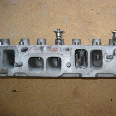
Lets look more closely at the 9 port heads. The most obvious feature is the siamese inlet ports, with the six cylinders grouped into three pairs and each pair sharing an inlet port. The valves are arranged like this: EI IE EI IE EI IE. Cylinders 1 and 2 share an inlet port, as do 3,4 and 5,6. Traditionally siamese ports have been considered unsuitable for high performance engines and in many cases (eg. BMC 4's) there is good reason for this. However, in the case of the Holden motor port sharing can hardly be blamed for the heads poor performance. If we look at the centre two cylinders (3&4) for example, we see they are 360deg apart in the firing order, and even with the longest duration cam there is never a time that both cylinders have their intake valves open at the same time. So obviously there is no chance for one cylinder to rob it's neighbour. The end pairs of cylinders are slightly different, and there is a short period during each cycle where one intake is closing while the other is starting to open. But this period is so short (and occurs at a time when there is so little flow) that any inter-cylinder influence will be negligible. It's not the fact that the ports are siamesed that hurts the flow, it's the basic design of the port along with that head bolt that passes through it.
The valves are all inline and only slightly canted and this, combined with the fact that the ports are quite low, makes for a sharp, almost right angled bend in the valve pocket area. Add to this a cast iron pillar that runs up the centre of the port near the gasket face and things are looking even worse. This pillar is where the head retaining bolt passes through, and is quite thick, almost a third of the port width. Over the years there have been several approaches to solving the head bolt problem, the most common being to cut the thick pillar out, replacing it with a thinwall steel tube. This is what YellaTerra did, and it's quite effective in increasing flow. Some people have cut the pillar out and installed a socket head cap screw in the floor of the port to clamp the head down, then screwed a flush fitting plug into the hole in the port roof. I doubt that there is much difference in flow either way, but the conventional steel tube approach is the most convenient.
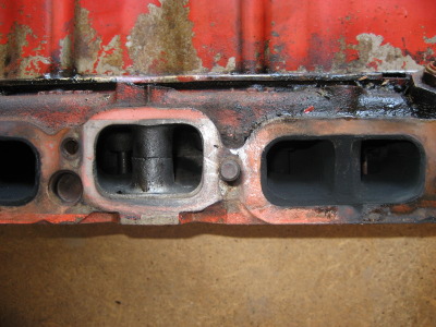 |
| Nine port head from a red 202. Note the thick bolt boss in the intake port. |
Fortunately there is a lot of meat in the port walls to work with, and it's easy to get big increases in flow and power output. If you're serious about making power, you should leave the port work to someone with the experience and equipment to get good results, and these people can get a 9 port head to flow enough to make over 310hp. In fact, in terms of sheer bulk flow you'll probably get more from a 9 port head than a 12 port, though of course bulk flow is only part of the story.
The standard valve sizes are too small, and you should aim to use at least XU1 or VH/VK size valves. The centres are fairly widely spaced, so there is plenty of room for bigger valves and seats. The downside to this is that the valves are very badly shrouded at the sides of the chamber, and it's pointless to try to widen the chamber because the side walls already overhang the cylinder walls. And anyway, there just isn't enough material between the adjacent chambers to lay the walls back much and still have sufficient thickness in between to support the head gasket. Of course the shrouding becomes worse as the valve size is increased, partially negating the benefits of using those big valves. Not only is the gas flow restricted by the chamber wall, it has to negotiate the ledge at the top of the cylinder bore. If you lay a head gasket on a cylinder head you will see that the openings aren't perfectly round, and match the shape of the chamber. Now lay the gasket on the block deck, and you can visualise the step or ledge under the chamber. Obviously the smaller the cylinder bore, the bigger the ledge, and it's a good reason to use the biggest available bore size. It's not uncommon to see these ledges on each side of the top of the bore chamfered or radiused back with a grinder to match the chamber, but if you decide to do this I'd be careful not to go too deep. The chamfer will definitely expose the part of the piston above the top ring to a lot of heat so I'd be wary of going more than about 3mm deep. You would expect that replacing this sharp ledge with a chamfer or radius would help flow - and nearly everyone does it - but to be honest I haven't been able to measure much improvement in flow. For a street engine I wouldn't bother.
We'll talk about combustion chambers more after we look at the 12 port heads as they are pretty similar with both types of head. If youre doing the head work yourself, all I can suggest is that you resist the temptation to make the ports huge and concentrate on slightly raising the roof of the ports, tapering them back from the port face to the valve bowl, so in effect the angle under the valve is less severe. Of course, you need to be able to match your intake manifold. Larger valve seats will have to be blended in and the bowl area can be opened up. The Holden ports are a bit unusual in that they seem to flow best when the bowl area is pretty much straight sided, and almost as big in diameter as the inside diameter of the valve seat.Don't grind the port floor at all, except to clean up any dags. There is no need for significant widening on any reasonable street engine. The biggest gains will come from fitting oversized valves, reducing the shrouding and from reducing the width of the head bolt boss. It isn't strictly necessary to cut it out and fit a steel tube, just narrow it and streamline it.
The earlier engines had intake valves of about 1.49" in diameter, and these are hopelessly undersized for nearly any application. Later red 202s and 173s had 1.625" valves, but these are still a bit small for anything but the smallest or mildest of engines. For a high output application you really need an intake valve of around 1.7" to 1.74" diameter. There's not much point going beyond this because the shrouding just becomes too tight and especially with the small chambers excessively big valves may actually flow less. The YellaTerra heads generally used valves 3/16" oversize.
 |
| Enlarged nine port intake with bolt boss and port divider removed. Either that or it's a two-car garage... Good flow; poor velocity. |
The exhaust ports flow quite well by comparison, and again there is plenty of meat to work with. There is a thick wall dividing the centre four exhaust ports, and these also have a head bolt passing through them. Unfortunately on some heads the wall doesn't quite extend all the way to the gasket face so these ports are at least partly interconnected, and I assume this would reduce the benefits of using tube headers or extractors. As with the intake, resist the temptation to go overboard with the grinder. Work out what size primary pipe size you will be using on the exhaust and match the port to this (keep it slightly smaller actually), trying to keep the cross sectional area fairly constant. Ideally there will be a step up of about 1 to 1.5mm all around the port into the exhaust manifold flange. You will probably find you will remove little if any wall material apart from a cleanup and some streamlining of the guide boss. The 1.275" exhaust valves of the earlier engines will be much too small, but you could get away with using stock 1.37" valves in a mild engine, and 1.48" blue/black valves will be big enough even in fairly highly tuned engines.
We can summarise the 9 port heads like this:
The standard head is extremely restrictive and won't make much
power no matter what other engine components you have
Siamese ports might be less than ideal, but on the Holden 6 the
firing order makes flow robbing from port to port a
non-issue.
An expert head porter can achieve massive flow increases, up to 300
odd hp, and even an amateur can get good results with care.
Oversize valves are necessary, but it's no use going overboard
because of the chamber shrouding.
There are many different types of manifold available for the 9
port, more than for the 12 port.
Twelve Port Heads
The introduction of the blue engines brought a completely new head design, and it some ways it was an improvement over the old red head, though it still could hardly be considered as high-performance. But where the red head sucked, the blue head sucked slightly less.. Obviously, there is now an individual port for each cylinder, and the exhaust dividers now extend to the port face so extractors will work properly. The valves are bigger, and there is improved cooling with some additional water holes. When fitting a 12 port head to a red block use a gasket as a template to drill matching holes in the block deck. The new intake ports are higher and narrower so the air flow now has a less severe angle to negotiate, though they are still much too low and too small. The intakes will probably look very familiar; they resemble a slightly smaller small block Chevy port.
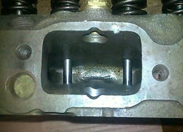
 |
| Twelve port head showing taller individual intake ports. |
Common wisdom has it that a stock 12 port flows about the same as a Bathurst style or YellaTerra 9 port head, though the few I've tested have flowed a bit less. They do have the potential for a fatter torque curve than that of the 9 port head though. The reason for this is that the individual ports allow the use of a true individual runner intake manifold such as is used with the EFI setup or six throat IR carb setup. The peak horsepower thus obtained probably won't be much different to the 9 port but the extra midrange will certainly boost performance. There is potential for flow improvement with these heads as well though they don't quite have as much scope for improvement as the 9 ports - although thats partly because the stock 9 port heads are so extraordinarily bad. If you want to make the most of them it's probably best to leave the port work to an experienced specialist. Unlike the nine port heads where nearly anything you can do is an improvement, you can easily reduce the flow of the twelve port heads if you don't know what you are doing (and yes, this is the voice of experience). Do-it-yourselfers could probably gain a bit by giving the ports a general cleanup though a flow bench is almost indispensible for this work. Don't increase the area at the gasket face - the port decreases in area by about 30% as it approaches the turn and any needless variations in area will just reduce the flow. Most of the increases in flow will come from unshrouding the valves and once this is done further gains can be had from some judicious grinding in the port itself. Just like the nine port, the bowl needs to be fairly straight sided with only a small neck down or venturi. Make it as big in diameter as practical but be careful with the long side radius. In the black heads this is quite a large radius, and the roof start to sweep down even before it gets to the guide boss. Don't shorten the radius or deepen the bowl too much or the flow will drop off dramatically. The port reduces in width fairly drastically an inch or so past the port face right up to the turn. This is a difficult area to open up but it becomes the point of restriction once the valves are unshrouded and the bowl opened up. The side wall near the cylinder centre can be made fairly straight while the opposite wall can be moved back a bit too. Don't get too carried away though or you will strike water. It really pays to cut up an old head or at least have a bit of a probe around with a wire through the water passage to determine how much meat you have to work with. At any rate, whatever you can do to reduce the change in area between the gasket face and the turn into the bowl will help flow. You can grind the first two-thirds of the floor to reduce the ski-jump effect but dont go too deep and drop the short side. You want to keep the bowl wall from the valve seat to the short turn radius as long and as straight as possible. It also pays to slightly widen and flatten the short turn so it blends more smoothly into the runner, but keep the actual radius short so as not to shorten the wall.
The exhaust port is also improved over the nine port, and as with the 9 port heads exits the head pointing slightly downwards. This might sound a bit odd, but I guess the idea behind it is to ease the transition into the exhaust manifold. The carb versions have bigger chambers and also have lumps in the roof of the exhaust ports where the air injection nozzles screw in. These can be plugged and ground back. Be careful not to enlarge the exhaust port as it will already be about the right size for a 1.5" primary tube, however it won't hurt to slightly streamline the somewhat chunky valve guide boss. Neither port has the wall thickness found in the 9 port head, so go easy with the grinder.
These heads have a reputation for being a bit prone to cracking, and the quality of the castings certainly doesn't look that flash. I think that the cracks might have more to do with the cars they were installed in than a problem with the head though. The old Commodores ended up having the radiator top tank lower than the cylinder head, so it was easy to get a pocket of air or steam trapped in the head, especially if the cooling system wasn't bled properly. The Nissan engines also suffered cracked heads in the same type of car, but were trouble free in other cars. The bottom line is this: get the head crack tested before you invest time or money in them, and if you have one of the old Commodores bleed the cooling system thoroughly.
The combustion chambers are very similar to the 9 port heads, and have the same problems with valve shrouding and the same step at the top of the cylinder bore. If you plan on using factory 12 port heads I suggest taking a look at the VK EFI version; they have better flow characteristics than the blue heads (by virtue of a multi-angle valve seat and face, plus a reshaped short-turn and floor) plus they don't have the air injection humps intruding into the exhaust ports. The downside is the big open chambers that do little for compression or squish. The blue 173s have a much better chamber, and these heads could be ported to give the same flow as the EFI head to give the best of both worlds.
As far as I know, YellaTerra can still provide 12 port heads.
These look quite good, with oversized valves and improved porting.
They are also said to be cast from better material. Keep in mind
that headwork doesn't come cheaply, so it's quite possible that a
complete new head will be cheaper than rebuilding and modifying a
used one. The biggest single disadvantage to using the 12 port
would have to be the scarcity of good intake manifolding. The
factory EFI works quite well, and even the factory 2 barrel
manifold would be acceptable for a mild daily driver, but what
these heads really like is a good, true IR (individual runner) type
manifold with three sidedraft two-barrel carbs. A good triple Weber
or Dellorto setup on these motors will be very quick, and should
make good power over a wide rev range. Select your manifolds
carefully; some are very badly designed will give disapointing
results. In particular approach anything that is claimed to fit
both 9 and 12 port heads with suspicion.
Unshrouding the Valves
In both types of head the valves are very badly shrouded, and the bigger the valve you use, the worse it is shrouded. At the outer side of the chamber it is impossible to get much more than about 0.1" of clearance with big valves, so the shrouding effect can never be entirely eliminated. On the port side of the chamber it's fairly easy to grind some clearance but to get the ideal means removing lots of material and therefore grinding into the water jacket is a real risk. The spark plug side of the head is where most of the flow will be at higher speeds, and again a lot of material will have to be removed so be cautious and study your cut-up head carefully. Use a head gasket as a guide to how far you can take the chamber wall. Of course this makes the step or ledge at the top of the cylinder bigger but the benefits of reduced shrouding far outweigh the increased turbulence from the ledge. Ideally the wall immediately around the valve head will slope back about 45 degrees, so that the distance from the wall to the valve is always about the same as the distance the valve is off its seat. In practice you mightn't be quite able to achieve this but it's critical that you get it as good as you possibly can. If you get the chance to run tests on a flow bench you will see that even minute increases in the distance from wall to valve will improve the flow. If you are fitting oversize valves consider using eccentric valve guides to shift the valve towards the centre of the cylinder. Even if you only shift the valve say 0.040" to 0.060" you will pick up useful gains in flow.
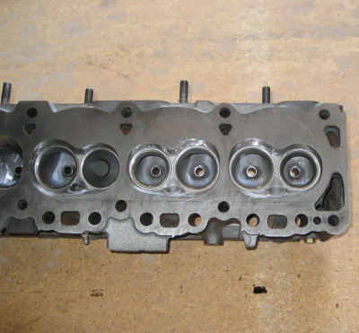 |
| Unshrouding large valves requires removing lots of material so take care to avoid making the chamber walls too thin. |
Relocating the Head
You'll probably find that the valve will still be slightly shrouded on the spark plug side even if you grind back to the gasket. What you can do to improve this is move the head towards the manifold side of the block by about 2mm. You will need to elongate the dowel holes in the head (don't just yank the pins out because they are needed to accurately locate the gasket) and also the bolt holes. Provided you don't get carried away you won't have too many dramas getting the water holes lined up, but don't forget to check pushrod clearance through the head. The extra couple of millimetres that can be ground from the sparkplug side wall will improve flow slightly and will also help enable further gains from port work.
Combustion Chambers
Promoting the maximum possible turbulence in the air/fuel charge is critical for efficient combustion. In more modern engines this is usually done by shaping the inlet ports to encourage swirl and tumble as the charge enters the cylinder. In our elderly Holden sixes though, we are more reliant on the combustion chambers squish pad to stir things up. There are useful power gains to be had by optimising the chamber shape - specifically, at TDC we want to reduce the clearance between the piston and the squish/quench pad to the bare minimum. This is the flat area of the head alongside the chamber bowl, and it's primary role is to induce turbulence in the chamber as the piston approaches TDC. It does this by "squishing" the mixture out of the confined space into the bowl area, but there is a downside to this as well. Because the mixture in this area is in such close proximity to the relatively cool metal of the head and piston, it doesn't burn along with the rest of the cylinder charge when the piston is at or near TDC. It either doesn't burn at all, burns only partially or only burns when the piston is significantly past TDC and it is too late to derive any usable work from it.
How much power can be gained? Lets look at an example engine, a 202 with 11:1 compression that makes about 220bhp. Lets assume the quench area covers about a third of the head area, and we have a piston to head clearance of 0.070". In this example the volume of gas in the quench area at TDC works out to about 12cc, or roughly 22% of the total chamber volume. In other words, about a fifth of the mixture in the chamber won't be producing any useful power. Lets say we reduce the clearance to about 0.35", so that we now have only about 11% of our available mixture in the quench area. In theory at least, we have just picked up over 20hp. In the real world of course the increase mightn't be so dramatic, but at any rate there are good gains to be made for very little effort.
Remember that the piston crown is part of the chamber, and any dish in the crown will have to be taken into account. Wherever possible, it will pay to use a flat top piston, or at least try to limit the dished area to that part of the crown that matches the bowl area of the head. How tight should the piston to quench pad clearance be? Basically you want to run as close as possible without actually having the piston smack the head at high revs. And that depends on how much piston rock there is at TDC, bearing clearances, thermal expansion of the piston and so on. You should be safe at 0.040", but I'd be nervous about anything less than 0.30". You can juggle the clearance by altering piston height, deck height or gasket thickness. Obviously, if there is any sign of piston/head contact you'd want to get a thicker gasket in there pretty quickly.
Valve and Seat Prep
This has a major impact on flow so it's important to get it
right. Both the 9 and 12 port heads can use a simililar
treatment.
Use 5 angles for the inlet, a 70 deg cut to blend into the throat,
a 60 deg bottom cut, 45 deg seat, 30 deg top cut & 15 deg
chamber blend with a 1/4" radius. Cut the chamber relief .125" out
from the edge of the valve (provided that doesn't take you out to
the gasket with a bigger valve). On the intake valve a 30 deg
backcut will help low lift flow.
On the exhaust use 3 angles. Make about a 3/8" radius off the seat
for the bottom cut, 45 deg seat, 30 deg top cut, 15 deg
blending/relieving cut with about a 1/4" radius. Like the intake,
relieve about 1/8" out from edge of valve if possible.
Notes on Porting
These are your choices:
- Grind away at the head, hoping for the best and then put it together and see what happens
- Buy, make or borrow a flowbench and test your handywork to be assured of good results
- Pay a professional that's experienced with these engines to port and flow test your head, and provide you with the flow figures
- Buy a complete, professionally built head from someone with a proven track record (eg. JZed or YellaTerra)
If there is one component on a Holden six that is absolutely critical to performance it's the cylinder head. Grinding away without the guidance or verification of flow testing could very well be just a waste of time. A ported head might look a million dollars but in reality be worse than a stocker.
Compression Ratio
There is no magic number here, the ratio needs to be selected with regard to the type of fuel used and also the cam timing. I'm not convinced that the petrol currently sold is as bad as some people make out, though there does seem to be some variation from batch to batch. Cam timing, and in particular the intake closing event has a huge effect on cylinder pressure and therefore compression ratio selection. At slower speeds, a delayed intake closing (such as is used with hi-po cams) will regurgitate lots of cylinder pressure back into the intake, making it possible - and desireable - to use a much higher ratio. As speeds increase and the engine gets "on the cam" the momentum of the intake charge causes this reversion to decrease or stop altogether, leading to much greater cylinder filling and pressure, and this in turn to a jump in torque and horsepower. At these higher speeds there is also a big increase in the amount of turbulence in the chamber, and this is why we can get away with the higher pressures at high speeds without detonation. It's also the reason that no more spark advance is required over a certain speed.
Despite all the other shortcomings of the Holden heads the chambers seem to support reasonably efficient combustion but even so I wouldn't get too greedy. As a very very rough rule of thumb, I'd suggest limiting CR on an engine with relatively short cam timing (similar to a stock cam) to around 9.5 to 1. Higher revs and longer cam timing will allow CRs of up to say 11:1 to be used with decent petrol, but if you are going to run high compression you'd better make sure you're right on top of the cooling, ignition timing and mixture distribution, otherwise it's easy to rattle the engine badly.
Builders of blown engines often have to reduce the ratio, and to be honest I'm less than impressed with some of the methods used. Things like pistons with deep circular dishes and decompression plates certainly reduce the pressure, but they kill any squish that may have existed in the chamber. This is just throwing horsepower away. If I was building a blower motor I'd be trying to keep the clearance between the piston and the flat face of the head to a minimum to promote turbulence (squish), just like in a normally aspirated engine. Then to reduce the CR, Id try to make the chamber deeper, possibly cutting a bowl in the piston that matches the head chamber but without touching the squish pad area. This approach should make significantly more power than simply spacing the head away from the deck.
For a naturally aspirated high-performance engine, you'll probably be using a small chamber head to get the desired ratio. Measure the chamber volume carefully to verify the ratio, the usual method being to cover the chamber with a piece of perspex with a small hole in it, through which you can pour light oil from an accurately graduated container or burette. You may need to machine material off the head to increase compression, and obviously if this is taken to extremes the stiffness of the head may be reduced to the point where it becomes difficult to keep the head gasket in. In these cases you may need to resort to o-ringing or domed pistons.
Here is the formula for calculating CR (the volumes for the
cylinder and chamber can be in cc or cu.in so long as you use the
same units for both. One cubic inch equals about 16.39cc):
CR=(D + V + DC + G + CC) / (V +DC + G + CC)
where:
CR = Compression Ratio
D = Displacement of one cylinder
V = Piston Volume (will be a negative value with a domed
piston)
DC = Deck Clearance Volume
G = Gasket Volume
CC = Combustion Chamber Volume
The formula to work out gasket or deck volume is:
V=0.7854 x d x d x g
Where:
V = volume in cc
d= Bore diameter in cm
g = gasket thickness (or deck height)
You can use the above formula with a slight modification to work
out how much a chambers volume will be reduced by if it's machined
by a certain amount:
V = 0.7854 x d x d x tm x ca
Where:
V = volume reduction in cc
d = bore diameter in cm
tm = the amount machined off the head in cm (10 thou is about
0.025cm)
ca = is the proportion of bore covered by the chamber bowl eg. if
the chamber area is about 60% of bore area use 0.6 for ca
Because there is so much possible variation in chamber volume from engine to engine it's important that the actual volume is measured so that the actual compression ratio can be calculated and adjusted if necessary. As a very very rough rule of thumb though, on a street engine you could reasonably expect to use a small chambered head (as used on stock 149/161/173/179/186 engines) on engines with 186cu in. or less. The smaller of these engines will probably need a little machining of the head to get the compression over 9:1. Engines of say 192 or 202cu in. or more will probably be better off with the bigger chambered 202 heads, probably with flat top pistons. One more word of warning - be very wary of piston manufacturers nominal CR ratings; there is a good chance that the actual CR will turn out to be quite different. There is really no other way but to measure and calculate the true value.
Induction - Carbs, Manifolds and Injection
What do we want from an induction system? How about this?
- A sufficient volume of air and fuel to allow the engine to develop its maximum potential power
- Fuel mixed thoroughly with the air, and in particle sizes uniformly small so they burn quickly and completely Uniform mixture distribution from cylinder to cylinder
Satisfying number one is easy; it's just a matter of making everything big enough . Number two is a bit harder, and seems to be particularly challenging for certain popular American carburetors. Number three depends mainly on manifolding, with some types it takes care of itself, others will take some work to get right. So how do we know when we have got it right? There are two key indicators, firstly the engine will make good power. And secondly it will have good fuel consumption relative to the power produced. I know this is supposed to be about high performance engines but it really is important to monitor fuel consumption as well; it's a sure sign of how efficiently the engine is running as a whole. Every now and again you might hear some young bloke tell you how he has built an engine so incredibly powerful he can barely back it out the driveway without refilling the tank. The correct response of course is to smile and nod, and to think to yourself: "You fuckwit. If you ever get that thing running properly it will make twice as much power and use a fraction of the fuel." Even a triple carbed, long-overlap cammed engine should give reasonably good mileage on the freeway, very similar to a stock engine with similar gearing if everything is set up right. So if your engine turns out to be thirsty in normal use, rest assured there is more power to be had by getting it to run efficiently. A good illustration of whats possible is the modern fuel injected engine; these are making much more power and torque than the engines of say 30 years ago, but at the same time using much less fuel and putting out less emissions. Burning every drop of fuel as completely as possible isn't just good for mileage, it's good for horsepower levels too.
Injection or Carbs
So which is best? It depends. A well sorted injection set up will outperform poorly done carburettors, just as well tuned carbs will run rings around badly tuned injectors. What it really comes down to is where your knowledge and experience lie. If you've spent years tuning SU's for example you could probably have an SU equipped engine running optimally pretty quickly. Conversely, if you know EFI inside out and have the right gear then injection is the obvious choice. While injection theoretically has a slight power advantage and is easier to live with day to day (if it's correctly set up) I think it's much more important to pick whatever you can tune accurately in a reasonable timeframe. In other words it's irrelevant which system has the most potential, what matters is which system you can get the most from.
Types of Induction Systems
We'll come back to injection systems later... in the meantime we'll check out the two basic carburetor/manifold layouts: common plenum systems and individual runner (IR) systems. We'll look at the IR systems first..
IR Manifolds
With these systems, each cylinder has it's own individual manifold runner and carburetor/injector butterfly. If you've had anything to do with multi-cylinder motorcycle engines you'll be familiar with these setups, they are like individual single cylinder engines on a common crankshaft. There are obvious advantages with regard to maintaining uniform mixture distribution, and its also easy to make all the runners the same length. Often it's also possible to make the runners relatively straight as well, and this helps reduce fuel separation.
One peculiarity of these systems is the "quick-gulp" intake characteristic - because each carb supplies only one cylinder there will be a period of roughly 270deg where the flow into the cylinder occurs followed by roughly 450deg of little or no flow before the next inlet stroke starts. And because the carbs are flowing only part of the time we need to use a total throat area of roughly three times that of a conventional system. This explains why these types of engines require carbs that at first glance appear to be way too big.
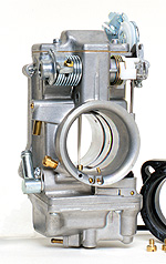 |
| The exceptionally clean flow of the Mikuni HSR helps to maintain both flow and velocity. |
Examples of IR manifolding include the traditional triple SU and Weber setups. Even though the 9 port heads have siamese ports the crank layout and firing order dictate that essentially only one valve in each port is open at a time, so in effect they run as an IR manifold. The 12 port motors are particularly well suited to IR manifolds as it's possible to use longish runners with a fairly constant cross section all the way from the carb to the valve. This can result in a useful boost to midrange power.
The triple Weber manifolds for the 9 port motors are a bit of a weird one - basically we have two carb throats and runners joining into a common port at the head face. In effect it's like two carb throats feeding each single cylinder. I know some people have had good results from these, but it hardly looks the most efficient way to do it, and I'd be careful to keep the venturi size down if I was using one of these manifolds. Old timers may remember one of the HDT Toranas at Bathurst, where the rules specified that the number of carb throats couldn't exceed the number originally fitted. This particular car had two huge DCOE Webers fitted - one throat had been blanked off while the other three fed the three siamese ports of the 9 port head. To me this is a more logical way of feeding a 9 port than using triple two-barrel Webers.
Weber (or Dell'Orto) carbs have for a very long time been considered the ultimate in Holden six carburetion (apart from the ocassional use of Amals), but I feel that there are now much better systems available. Modern flat-slide carbs such as Mikuni's HSR series are aerodynamically much slicker, and flow extremely well while maintaining a high velocity. Originally designed as a performance carb for Harley Davidsons, they cope very well with the severe pulsing of an individual runner layout. Six of these on a 12 port head will perform exceptionally well, while three on a 9 port head will provide a much cleaner flow path than the usual DCOE on each port. A further advantage is that almost any length runner is possible with the Mikunis, whereas with the Webers it may be difficult to get suitably short runners on a high revving engine, at least without having fairly severe kinks in the runners. If you decide to try these be careful with the sizing - a 45mm (for example) HSR will flow much more than a similarly sized throat on a DCOE.
To summarise, IR setups generally give very good results, but are more expensive and require a bit more work to synchronise the butterflies and tune properly.
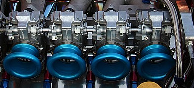 |
| This Nissan engine has four Mikuni HSR carbs fitted to an IR manifold. Probably the best currently available carburetion. |
Common Plenum Manifolds
This is where all the manifold runners connect to a common chamber that is fed by a carburetor or carburetors. The stock single carb layout is an example. Provided the carb and the runners are big enough bulk flow shouldn't be a problem, but maintaining good distribution can be a challenge. In the old days it was common to fit dual or triple Stromberg downdrafts to the old Holdens, and I suspect the improvements these brought were as much a result of better distribution as the increase in flow. They have the advantage of simplicity, and because the carburetor isn't subject to the violent pulsing that can occur in an IR setup they can be a bit easier to jet for clean running over a wide rev range. On the downside it's almost impossible to make the manifold runners the same length, and curves in the runners are unavoidable. Fuel drop-out is a problem, and this is the reason most factory manifolds are heated. The heat does wonders for smoothness and mileage, but it reduces the power output.
In summary they are relatively cheap and simple, but with limitations regarding runner lengths and distribution.
Downdraft Common Plenum Setups
For the best performance, I tend to think one of the sidedraft setups are the way to go, though I guess if you were trying to keep an engine looking reasonably stock or you just want to keep it simple a downdraft setup might fit the bill. For mild daily drivers the Weber from the 3.3l XE Falcon works very well with a 12 port head and stock manifold, though it's a bit small for very high performance work. Even the stock Varajet flows more than a 350 Holley, and can make reasonable power but the downside is that there are few people familiar with these carbs, and jets and rods aren't as readily available as they are for other carbs. If you're willing to spend some time with them though, they can work well.
For higher outputs, some people have had good results with a small 4 barrel carb on a 9 port motor, but whatever you do steer clear of the 350cfm (or 500cfm) two-barrel Holleys. A Holden 6 with a well sorted Holley 350 will start and idle well, run cleanly and produce a moderate amount of power. But it will also use more fuel than the other small two-barrels, without any power advantage. They obviously have a pretty severe problem with mixture quality and/or distribution. I suspect that this is due more to the orientation of the carb rather than any problem with the carb itself - a peculiarity they have compared to the other 2 barrels is the butterflies open together, and they swing open on an axis that's at right angles to the engine. Maybe this contributes to the poor distribution, and it would be interesting to try one rotated 90 degrees on a four barrel manifold. I know there are a squillion blokes out there with Holley equipped sixes, and they all swear that their engines run just fine. Which they do of course, but I'd bet good money that they would make significantly more power and use less fuel with a different carb.
While we're on the subject of Holleys, be aware that the two barrel carbs are rated at twice the pressure drop of the four barrels (3"hg versus 1.5"hg), so the 350 (and even the 500) two barrel will be undersized on anything but a fairly mild motor.
Although downdrafts mightn't be the ultimate in performance, a decent two-barrel on a stock 12 port manifold is a cheap and simple solution for a mild street engine. For higher performance a four barrel will provide sufficient bulk flow for good peak power but it will be difficult to match the mixture quality and distribution of a set of triples. Good results have been had from 390 and 465cfm Holley 4 barrels, and for a full-on drag engine it might be possible to use anything up to a 600cfm carb.
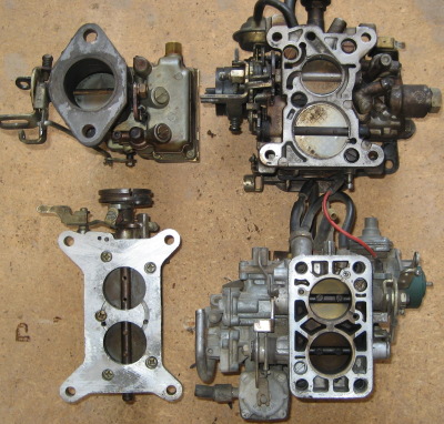 |
| Various throttle bores compared. Clockwise from top: Stromberg single throat from red 202, Rochester Varajet from black 202, Weber from XE Falcon, 350 Holley. Varajet flows a bit more than 350, the Weber just a tad less. |
CV/CD Carbs
By CV carbs I mean the constant velocity/constant depression carbs such as the SUs or Zenith/Strombergs as fitted to the XU1s and any number of pommy cars. And I may as well say right now that there is probably no performance advantage to be had by using one brand over the other. There may be a minor advantage to the SUs in that their piston design eliminates any potential diaphragm problems. I've used CV carbs on a variety of engines over the years, and they have never failed to give excellent results.
It's practically impossible to overcarb an engine with CVs, and they seem to tolerate being fitted to overcammed street engines very well. Inch and three quarter CV carbs are almost the defacto standard on a hot six, and they will certainly perform well on a very wide range of engines from near stock to quite high outputs. On a very well breathing 186/202 it may pay to go for 2" units to achieve the engines full potential, and unlike fixed venturi carbs there will be no penalty from using the bigger carbs as the throats only open as far as necessary.
Some people are wary of using these carbs because of their undeserved reputation for being hard to tune and/or keep in tune. The reality is that as long as the spindles and linkages are in good condition and well set up they require very little attention at all. There must be no play at all in the bushes or rod ends, and the main shaft must be set parallel to the throttle spindles. Also it pays to run individual return springs directly on each butterfly to minimise the effect of any play in the links. Once the carbs are synchronised and the mixture set they will run for a very long time without any further fiddling. While there is a huge variety of metering needles available it's very likely that the factory fitted needles will be very close to ideal, and it seems that the standard needle can cope with a wide variety of engine types.
Summary: CV carbs will give excellent results on nearly any engine.
Port Matching
Careful matching of the manifold ports to the cylinder head ports can help prevent flow losses at the head/manifold interface. It sounds simple enough but there are a few things to keep in mind. Firstly, be wary of using the often recommended method of using the gasket as a template to mark out the ports. The gaskets are often a bit oversize so you can end up with a short section of the port on either side of the joint where the port area needlessly increases before reducing again. Obviously this won't do much for flow. The other thing to watch out for is accurate location of the manifold - it's pointless making the ports match exactly if the manifold can move around and you can't see whether the ports are aligned. Things like alignment dowels or extending the locating lugs will help here, and you can check the alignment by using a blank gasket and thinly smearing the head and manifold faces with bearing blue to indicate the mismatch.
Where the manifold runs into the head in a fairly straight line it's best to match the ports exactly (provided of course that it is accurately located as well) or else make the manifold opening just a little smaller than the head opening - a step-out of around 0.5 to 1mm all around is OK. If there is a curve in the runner at the gasket joint - as is common with downdraft manifolds - try to have a 1mm or so step-out on the long or outside wall and match the others as closely as possible, but whatever you do avoid creating ledges or step-ups going into the head. It's always best to have the manifold slightly smaller if it can't be matched exactly.
The techniques above apply mainly to applications where performance is the primary goal; on a mild street engine I wouldn't worry too much about getting a perfect match. And if fuel economy is the goal, then a small step up into the head port is actually beneficial. A small but sharp-edged step won't reduce flow that much but it is very effective in shearing any wet fuel that has collected on the runner floor back into the airstream, and may allow the use of slightly leaner jetting.
Tuned Length Intake Runners
Just like on the exhaust side, there are torque gains to be made simply by making the intake runners the appropriate length. With side-draft carbs it's fairly easy to modify the manifold or even make a new one from scratch, though with a downdraft you might just be stuck with what you've got. And anyway, with downdrafts it will be difficult to make the runner lengths anywhere near equal.
Basically a low speed engine will want very long runners while a screamer will want them very short, and obviously there is an infinite range in between. There are formulae to calculate the ideal length, or alternatively one of the engine simulation software packages (eg. Engine Analyser) can guide you. Keep in mind that the length includes the intake port in the cylinder head. While the correct length can provide substantial gains it's not absolutely critical to get it right down to the last millimetre - if its within say 20mm you'll get close to the best possible performance. As a very very rough guide a quite mild street engine with a torque peak around 3000rpm will like a very long runner - up to about 400mm or so. A hotter engine with a torque peak at say 5500rpm will probably want a total length of 200 - 250mm, while a hotter engine again will want a total length of only 150 - 175mm (and remember this includes the head). High revving engines with triple Webers may well benefit from experimentation with slightly shorter runners than are commonly used.
Mechanical Injection Systems
Back in the heyday of the Holden six mechanical injection systems were often fitted, mainly for speedway or drag engines. Probably the most commonly used was the Australian-developed McGee system, though other manufacturers components can be used as well. These systems can (and have) been used on the street though it's not recommended for reasons we'll cover later. They have the advantages of simplicity and ruggedness, and are not affected by G forces, unlike carbs. Performance wise, they are unlikely to show much if any advantage over a well-developed carb system, though it might be easier to use appropriately sized intake runners with injection.
They basically consist of a vane type pump driven from the engine, a barrel valve linked to the throttle butterflies and a set of injector nozzles. The pump flow is in direct proportion to the engine revs, and the barrel valve directs excess flow to the tank depending on throttle position. Full throttle mixture is set by the size of a by-pass "pill" or jet that meters return flow from the nozzle manifold block back to tank. Because the engine will usually require less fuel either side of the torque peak it is usual to use additional bypass jets for both idle/low speeds and high speeds. These are constant flow systems, with all the nozzles being plumbed back to a common manifold block.
Nozzle size should be the smallest that can be used while keeping full-throttle/high-speed fuel pressure within reasonable limits. Mixture quality at medium to high speeds should be fairly good, but at idle and lower speeds the nozzles will be dripping and dribbling rather than spraying. For this reason much of the fuel will pass through the engine unburnt at low speeds so to maintain a burnable A/F ratio much more fuel will have to be injected than should normally be required. The engine may run cleanly enough but it's quite likely that excess fuel will be washing the cylinder walls at low speeds and this is the main reason to avoid using these systems on the street. Fuel economy is also likely to be very bad on a street engine.
For a competition engine - especially on methanol - mechanical injection can give good response and power output while being simple, rugged and virtually immune to acceleration, braking and cornering forces. For precise metering over a very wide range of speeds and loads however, EFI or a carburettor is usually a better choice. J.Zed (see links section) can supply complete mechanical systems to fit the J.Zed head or Sonic Injection can supply throttle bodies/manifolds to suit the 9 port Holden head.
Electronic Injection
The only complete off-the-shelf EFI setups for the Holden six that's suitable for competition use that I'm aware of is the one made by Sonic Injection (see links section). For accurate metering over a wide range of speeds and conditions, a well tuned EFI system will be unbeatable - but note the use of the words "well-tuned". A poorly tuned EFI will be just as bad as any poorly tuned system.
Because the injectors regulate the amount of fuel injected by varying the amount of time they are open (rather than by varying supply pressure) it's possible to get a good spray pattern and mixture quality even at very low speeds and at idle. Injector pulse width is determined by the ECU, which calculates the value using inputs that may include mass air flow, manifold pressure, throttle position, crankshaft speed, coolant temperature etc. Systems for competition use are often simplified to use only crank speed, throttle position and/or manifold pressure.
Building and tuning a good EFI system will cost a bit more than say triple Webers and it does add some complexity, but because EFI is so ubiquitous on modern cars EFI expertise is probably now more widespread than that for carbs. Interestingly a carburettor will often show as much power on a dyno as injection, but on the strip a properly tuned EFI will be markedly quicker. In summary, a well done EFI system will provide the best performance in nearly any application.
VK Commodore EFI Systems
The EFI from the VK can perform very well, despite being very simple - almost to the point of being crude. The system has few inputs, and has no feedback devices such as oxygen sensors etc. The injectors are wired in two groups of three, but all fire simultaneously at 120deg intervals. The manifold design provides very good midrange torque and is suitable for engine speeds up to about 5500rpm - ideal for a strong street car. A bit of judicious portwork at the transition area leading up to the gasket face should pay off with even more flow and power. The relative crudity of the fuel control makes the fuel economy from these units less than spectacular and in fact better economy can be had from the Varajet equipped engines. Improvements to the controls make these units perform even better, with gains in both power and economy. There are limitations with the stock ECU with regard to compatability with longer duration cams. Aftermarket, tunable ECUs are readily available though, as are bigger injectors and throttle bodies etc. A popular budget mod is fitting the 808 Delco ECU from the JE Camira. These are cheap, programmable (using something like Kalmaker) and able to use additional inputs such as exhaust oxygen sensors. I won't go into much detail here on EFI's but there are plenty of people out there who have used these successfully, and there are some good how-to's on the web.
The strong point of the EFI system is the midrange torque provided by the long manifold runners, and this manifold also works very well with LPG. For an LPG-only engine the compression ratio can be raised to make up for the slight drop in output that LPG normally brings. There won't be any distribution or fuel drop-out problems and you'll get a nice flat torque curve...
Be aware that the EFI manifold becomes quite restrictive at higher revs and flow rates - say around 5500rpm/180hp and up. There is a substantial reduction in area for a distance of about 100mm back from the gasket face, and there isn't enough wall thickness to open them up without first building them up with weld. And even if you did open them up it's likely that the runners would be too long for high rpm work anyway. For practical 12 port street car projects though, a VK EFI may well be the best choice.
 |
| VK EFI manifold sectioned to show the 40mm ID runner entries. |
 |
| This shot shows how the manifold runners neck down as they approach the head. |
Air Filtration
To ensure your engine lasts for any length of time you will need effective air filtration, and that means paper filters. Oiled cotton filters flow quite well but are poor at filtration. Foam usually does very poorly at both. Paper is the best at filtration but needs a big surface area to maintain sufficient flow; large paper elements are the best all-round choice. When using IR type manifolds the quick-gulp flow characteristics that require relatively high capacity carbs will also dictate higher capacity filters. Small individual filters on each carb are unlikely to be big enough. It's probably better to duct all the intakes together into a common airbox and use a single BIG paper element. Also keep in mind that at low speeds a long duration cam might spit back a bit of fuel, so try to keep the filter far enough away from the carb inlet that the element doesnt get wet. Realistically I know that space limitations make all this difficult, but if you can set up a good filter system you'll maximise both horsepower and engine life.
Fuel Pumps
Obviously an adequate fuel supply is essential, but that doesn't necessarily mean swapping out the stock pump. These were used successfully at Bathurst on fairly high output engines so they can't be all that feeble. If you think you'll need more flow a small block Chev pump is a direct replacement. I tend to favour mechanical pumps for reasons of quietness and reliability, but an electric pump is fine too so long as the pressure and flow ratings are suitable. SU's in particular don't like any more than a couple of psi fuel pressure and will dribble and puke if overpressurized, so use the appropriate regulator. And don't forget to use a good quality filter.
If you're building a quickish car, it will pay to work out the fuel
requirements of the engine to ensure an adequate supply. Many instances
of top end power loss have been cured through increasing the fuel supply; on the other
hand there are many moderately powered cars around with fuel systems that would
be more at home on a 1200hp Pro Stocker. Engine design software will show
how much fuel is required, or you can use the following rules-of-thumb:
Normally aspirated engines need a minimum of 8usgph for every 100hp; round
this up to 10usgph/100hp for a safety margin. I've used US gallons as the unit
here because most of this hardware is US made. Adjust or convert as required.
People often talk about adding pressure to allow for acceleration g-forces, but realistically these will be negligible for most full-bodied Holden six powered cars. It works out that for every 1G of acceleration and 3ft of horizontal line length you need to add 1psi. For example, if the car accelerates at 1.5g and the distance from the pickup to the forwardmost end of the fuel line is 9ft you'd need to add 4.5psi to the pump pressure. Provided the regulator (if used) is mounted near the front of the fuel line there is no need to increase its setting to counteract G forces, only the rear mounted pump setting is affected. Keep in mind that g-forces will also have a siphon effect on return lines; specifically it can artificially reduce the regulators pressure while under acceleration. It's possible (though unlikely) that it will be necessary to use a check-valved vent to negate the siphon effect with some systems.
Camshafts and Valve Gear
The limitations of the Holden cylinder head have a big influence over the cam profile selection. Because the port design and the tendency for the valves to be shrouded limits the high-lift flow, it's important to get the valves opened as quickly as possible. In other words we need to get as much area under the curve as we can without making the duration ridiculously long. The downside to using such aggressive profiles is a reduction in cam lobe and lifter durability, but really if you want to get the maximum performance from the engine you don't really have much choice but to smack the valves open and put up with the shorter cam life. Like many GM engines, the Holden engine would benefit from a camshaft with bigger journals and a bigger base circle diameter - with flat tappets there are limits to the lift and valve acceleration rates that are achievable. In this respect a roller type cam would have a decided advantage, though I'm going to conveniently ignore them here as being outside the scope of these basic notes. If you have the time and money to use rollers though, it would certainly pay to discuss them with a reputable cam grinder as they will provide not only a higher peak power level but more area under the torque curve as well.
Basically we are going to have to choose beween hydraulic or solid flat-tappet cams. Common wisdom has it that any street driven vehicle should run a hydraulic cam, but there are some very good reasons to go with solids. Everyone knows solids aren't susceptible to the lifter pump-up issues that hydraulics can sometimes suffer from. But there is also a substantial performance advantage that goes with solid lifter profiles. Hydraulic lifter cam profiles need to have a short but gradual ramp just before the valve acceleration starts in earnest. The same thing happens on the closing side. The net effect is that, for a given duration at 0.050", a hydraulic cam will hold the valves off the seat for longer than a solid lifter cam will. These ramps are so gradual that no useful flow occurs, but it's enough to bleed off cylinder pressure at lower speeds. By contrast a solid lifter cam will leave the valve firmly on its seat before slapping the tappet rudely. In other words, for a given peak horsepower, a solid lifter cam will give a stronger low end and midrange than a hydraulic cam. Or looked at in yet another way, for a given low or midrange torque, a solid will give a better top end.
Hydraulic lifter cams do have a couple of advantages though; they are quiet and maintenance free, and if performance isn't the primary consideration they could be a logical choice. They also don't require adjustable rocker gear. The factory VK EFI cam is an excellent hydraulic grind for a mild engine, but of course any of the original cams will be very badly worn by now. Also keep in mind that the cams in the later engines were set up retarded a few degrees to help with emission control so if you use one you might like to install it "straight up" for stronger bottom end torque. If however performance is the priority, definitely go for the solids. They have a reputation with some for needing constant adjustment, but in reality once everything is bedded in they should rarely need attention. Millions of engines are fitted with solid lifters as standard and these often go for years between adjustments. Granted, the stresses on a high revving Holden 6 valvetrain might warrant more frequent setting, but a few times a year should be enough. Besides, adjustment is much easier and quicker to do on the 6 than say a V8, so it doesn't take long at all.
When comparing cam profiles between different manufacturers check the duration at 0.050" only, the advertised duration figures are too "rubbery" to be meaningful.
Some very very rough rules of thumb for cam selection:
Longer duration = more top end, less bottom end
More lift for a given duration = more area under the torque
curve
Closer lobe centres/more overlap = more bottom end and less on top
(but more overlap also makes for rougher light throttle running and
idling)
Wider lobe centres = better top end at the expense of low down
torque, better light throttle running and idling
Slightly retarded cam timing = more top end, less bottom
Slightly advanced = more bottom end, less on top
Did you notice the pattern there? Anything that results in the intake valve closing later will move the torque peak up the RPM scale, and vice-versa. Of the four valve events the intake closing is by far the most critical - you can shift the other three around a bit and it doesn't really make much difference to the power curve, but as soon as you shift the intake valve closing point the curve will also shift.
So what cam to use? Here is another very rough guide:
Mild daily driver, smooth enough for granny - 200 to 210deg @
0.050", 0.39" to 0.41" lift (hyd)
Slightly warmer, rough idle but still fairly civilised - 215 to
225deg @ 0.050", 0.4" to 0.44" lift
Hot barely streetable cam - 230 to 240deg @ 0.050", 0.44" to 0.48"
lift
Bigger again, maybe just barely streetable for occasional use by a
masochistic driver - 240 to 250deg @ 0.050", 0.490" to 0.5"
lift
Animal, dont even think about trying to use it on the street
-250+deg @ 0.050", 0.520" to 0.570" or more lift
The engine capacity also has some influence on cam selection; a cam that is "big" in a 202 will behave even "bigger" in a 161. Or put another way, a cam profile that produces peak torque at a certain speed in a large engine will peak at a significantly higher speed in a smaller engine. Bottom line: don't kill the bottom end torque of a small engine by using too much duration. We mentioned this briefly in the Planning section but it bears repeating: the cam profile must be selected with the available gear ratios in mind. It's very easy to overcam the engine in the pursuit of horsepower, and while the dyno numbers might look impressive it may well be impossible to keep the engine pulling hard on the track with less than six gears. Do your sums carefully - it's very likely that you'll have to use a relatively conservative cam to get the most performance from the commonly used transmissions.
When you get the cam, make sure you get all the related components from the same manufacturer so that you can be sure the springs, retainers and lifters etc. are compatible. You may need to make the spring seats bigger/deeper for big springs and high lifts. If you aren't sure how much material is in the spring seat area do a practice run on an old head first or cut an old head up to see how much meat is in there.
Drive the cam with an alloy or steel gear, but for chrissakes don't use those damn straight cut gears - their only virtue is their cheapness and the constant whining is irritating. The claims that the helical gears sap power are drivel. The only time I would consider straight cut gears is on a very high rpm engine with extreme valve spring pressures. These engines tend to have a fair bit of torsional vibration of the camshaft and with helical gears they rattle against the thrust faces and scatter the spark timing a little. For anything not so extreme I'd stick with helicals though.
Don't try to be clever with cam timing; at least to start with set it exactly where the cam grinder intended it to be run; you can experiment with minor variations later. If you need to reposition it more than a few degrees for best performance you've got the wrong cam... Carry out all the usual precautions ie. check for coil bind, retainer to guide clearance, valve to piston clearance, rocker slot, etc etc. As well as all these checks, you'll also have to check for valve to deck clearance because of the chamber overhang. The press in rocker studs are good enough for a mild engine, but use screw in studs for setups with higher lifts and heavier springs.
The factory rocker setups are fine with any reasonably streetable cam, though you'll need some form of adjustment for solids. Roller rockers are nice to have with bigger cams, say over 0.45" lift, and the shaft mounted jobs eliminate stuffing about with guideplates. If you run ball-mounted rockers (or stud mounted rollers) on a head that originally had aluminium rocker bridges you will need guideplates and hardened pushrods. Standard rockers are 1.5 ratio, you may find rollers in other ratios or adapt rockers from other engines (eg Cleveland). Be aware that higher ratios increase the loading on the entire valvetrain so while they definitely improve performance there is a tradeoff in durability. If you decide to try the cheap Chinese rollers carry a couple of spares in your toolbox, and pray that when they fail you catch them before they dump a million needle rollers throughout your engine.
There is a difference in the length of pushrods used with ball mounted rockers versus the later non-adjustable rockers, so be careful when mixing components from different engines. You should also take the time to get the rocker geometry right; with so many things like deck height, cylinder head dimensions, cam profile etc. being altered it's quite likely that a non-standard pushrod length will be required. At the mid-lift point, an imaginary line drawn from the valve tip contact point through the centre of the rocker pivot should be perpendicular to the valve stem. Shaft mounted rockers have an advantage here as the pivot post can be machined or shimmed to correct minor discrepancies.
Holden lifters should be used, even though there may be others (eg. Chev) that will fit. The reason for this is that the other lifters may not have the relieved section in the right position on the body, and could possibly cause a major loss of oil pressure.
Follow the manufacturers cam break in procedure closely and make sure you use an oil with sufficient zinc additive to protect highly loaded flat tappets, eg. Rimula Super or Valvoline Racing. Most modern petrol engine oils aren't suitable, and using them will lead to cam and lifter failure.
Keep in mind that many of these cams will provide insufficient vacuum for brake boosters and so on - you may need to provide a separate vacuum source such as an electric pump or an alternator from a Japanese diesel with a built-in vacuum pump.
One more rule-of-thumb: if you can't choose between two different cams always go for the milder one. An overcammed street motor will be slower than it should be, and more painful to live with.
Exhaust
The exhaust has a profound effect on performance, but to get the maximum returns can take a lot of work. There are two basic requirements: firstly we want a system that offers free flow with a minimum of backpressure, and secondly we want tubes dimensioned to provide the best possible scavenging and power output. Before we get to specific sizes, let's take a quick look at how the exhaust works.
Imagine the piston descending on the power stroke. Somewhere after midstroke the exhaust valve begins to open, and the gas, still under a fair bit of pressure, starts to flow. By the time the piston is at BDC the pressure will be mostly relieved, and as the piston rises it shoves more gas out the exhaust port. Clearly we can see that excessive backpressure will incur a horsepower penalty because of pumping losses, but in fact the losses due to pumping are fairly low, even with substantial backpressure. Despite this there is a good reason to limit backpressure: not only does the remaining gas occupy volume that could be filled with fresh mixture, but when the intake valve opens as the piston approaches TDC the backpressure-compressed gas flows back up into the intake port, further contaminating and diluting the fresh mixture.
The real power gains are made through better scavenging. Imagine that the piston has now reached TDC on the exhaust stroke. The gas in the cylinder has been swept out, but we still have a body of exhaust gas occupying the combustion chamber - depending on the compression ratio it could be about 10% or so of the cylinder volume. Unless we can get rid of it the gas will rob space that could be filled by fresh air/fuel mixture, plus it will dilute and contaminate the mixture, slowing combustion. The way we get rid of it is with an efficient exhaust system that uses a mixture of inertia forces from the moving column of gas and sonic activity to literally pull the remaining exhaust gas from the chamber. Of these two forces, the sonic or sound wave action is the strongest. A good illustration of the ability of sound waves to produce power is the two-stroke racing motorcycle engine - these have extremely high specific power outputs that are largely made possible by their expansion chamber exhaust systems.
So how do we make it work? Firstly (and this is a grossly simplified explanation but it'll do for the time being) we use a primary pipe diameter that provides sufficient flow velocity that the momentum of the column of moving gas helps pull the remaining gas from the cylinder as the piston slows down approaching TDC. This is a compromise of course between getting a high flow velocity and keeping the friction losses and therefore the backpressure down. Secondly, we try to make the primary pipe the right length so that as the piston approaches TDC a negative pressure wave is returned from the collector and arrives at the chamber at just the right time to drag the last of the exhaust gases out and get the flow started from the opening intake valve. Of course with an exhaust system of fixed dimensions this can only work well over a fairly narrow RPM range, so it's important to match the exhaust system to the other engine components.
Sound waves are created when the exhaust valve first opens, and a positive pressure wave will travel from the exhaust valve down the primary pipe. Whenever there is a change in cross-sectional area, another sound wave will be reflected from that point back to the source. If the cross-sectional area decreases then the reflected wave will be the same sign or polarity as the original wave ie. if a positive pressure wave hits a reduced pipe area then another positive wave will be reflected back. If however the pipe increases in area, then the wave is reversed in "polarity" and a negative pressure wave will be bounced back to the chamber. This is basically how a typical collected extractor works then: the momentum of the gas column helps pull gas from the cylinder as the piston decelerates. Then the original positive wave produced when the valve first opened will be bounced back from the point where primary pipe meets the collector as a negative pressure wave at just the right time to scavenge the chamber. Providing of course the length is right. It all sounds neat and tidy in theory, but it's not quite so simple in reality. In a real exhaust there will be other changes in cross section besides those at the collector, where other cylinder pipes branch into primary pipes for example. As well, there will be pressure waves from some cylinders setting up waves in pipes from other cylinders and the end result is that there are dozens of waves of different signs and amplitudes rattling back and forth in the system, some beneficial, some not so. Get the dimensions right though, and it all works rather well.
OK, so much for theory, what size pipes do I need for my 202? Well that depends. A tuned system can only work well over a fairly narrow rev range, so for a mild to moderate street car that operates over a wide RPM range I wouldn't even bother with sonic tuning. I'd simply use a set of off-the shelf extractors with the appropriate primary pipe size. In fact, for engines up to about 160hp the factory dual outlet cast manifolds will often perform as well as extractors. The dual manifolds were made for some of the red engines (186S for example) and were standard on all the blue/black engines. Compared to tube extractors they are cheap, quiet, leak-free and long lasting, so don't discount them for the daily hack.
How then do we design a system for a high output engine with a narrow rev range? We need some starting point for the dimensions in order to reduce experimental cut and shut to a minimum. Designing a tuned system can involve enough calculations to fill a book, and indeed there have been several books written on the subject. The easy way - and I love easy ways - is to use software to do the sums for you. Any of the engine simulation programs can do this, plus there are programs specifically for pipe design as well as free online calculators. Interestingly, if you use several of these to design a system for the same engine you'll find they don't all come up with exactly the same dimensions. They will however come up with figures that will be close enough to get you started, and the experimental optimization work will be kept to a minimum should you choose to do it.
OK, here's another very very rough guide: for smaller engines (say less than 179ci) of up to 120 - 130 hp use 1.375" to 1.437" primary pipes. It may be difficult to match your exhaust ports to these small tubes and if so don't stress, just use 1-1/2" pipes. For engines of 130 to about 200 hp use 1.5" tubes. From 200hp to about 275hp 1-5/8" pipes will be about right, and once you go from 275hp to well into the 300's (probably not with a Holden head!) you could probably even make good use of 1-3/4" tubing.
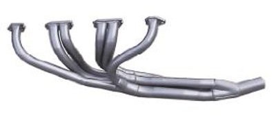 |
| HM Headers HM9C - widely regarded as the best off-the-shelf competition headers |
As for primary pipe length you really need to calculate this for each individual engine as it is influenced by valve timing as well as other factors. Engines at the high end (torque peaks above 6000 -6500rpm) will probably like about 27 - 28", more moderate engines around 30" and streetable engines around 32 - 34", though really you should calculate this yourself or use the appropriate software. Ideally all the primary tubes should be exactly the same length, and most off the shelf extractors will have quite a lot of length variation. Having said that, I'd rather have extractors where at least some of the tubes were roughly the right length than a set where all the tubes were the same incorrect length. The straight six has much more room to fit exhaust manifolding compared to a V8, but even so you may come across primary pipes that dive down at a sharp angle right from the port face. Wherever possible leave a few inches of straightish pipe at the flange before sweeping the pipe down, remembering that the exhaust port in the Holden heads is directed down at a slight angle. Check the port match at the flange and head face, some extractors are way off and will need a bit of work with the die grinder.
To continue our rough and somewhat dodgy guide over at the collector end, you'll probably find good results using a collector with an area of roughly 3.3 to 3.4 times the primary pipe area. Thus for 1-1/2" pipes use a 2-1/2" to 2-3/4" collector, for 1-5/8" primaries a 3" collector, and for 1-3/4" pipes a 3-1/4" collector. If you have time to spare you may find you can broaden the powerband somewhat by making the collector tapered, ie. make the collector entry area about 2.5 times the primary area, with the outlet area about 3.5 times the primary area. To make this work you would need to merge the primaries together gradually (the so-called "merge-collector" design) and this isn't a bad technique to use to merge the primaries together anyway. The collector length isn't as critical as the other dimensions, and if you use a length equal to about 5 or 6 diameters you'll be close.
If you need to run a full system with tailpipe and muffler these need to be as big or a tad bigger than the collector to maintain power. The downside to running such a big system on a street car is that they tend to be "boomey" and the drone quickly becomes annoying. It may be better to run a smaller, quieter system on the street that can be quickly disconnected at the strip. Popular opinion states that pipes bigger than 2-1/4" or 2-1/2" will reduce low rpm torque, but these pipe sizes will be too small for high output engines which may require anything up to a 3" system. I know from experience that some engines feel stronger down low with a smaller pipe, but I suspect this is an illusion caused by the smaller, quieter pipe. Best performance will come from using a pipe sufficiently big that it appears to the engine to be dumping straight to the atmosphere from the collector. As mentioned earlier though, such a big system may be difficult to accomodate and be annoyingly drummy.
Big, baffled mufflers are quieter and sometimes flow as well as or better than the straight-through absorbtion types, even though they are more difficult to accomodate neatly. OEM mufflers from late model injected engines of a similar or (preferably) greater output should perform well, at least as well as the so-called sports designs, and should be cheaply available from the wreckers. Single systems are generally regarded to be best from a performance perspective, though it should be noted that manufacturers such as BMW have fitted dual exhausts to their cars as standard - and if anyone knows high performance straight sixes it's BMW. Their use of dual pipes may be more due to the fact that it's sometimes easier to fit two small pipes rather than one big one though. Regardless, I would stick with a single system unless I had a very good reason to do otherwise.
If there is one piece of advice you should follow it is this: don't just guess the exhaust dimensions or use what worked on your mates engine. Use something like PipeMax to calculate the sizes so you can be confident of being fairly close to the optimum right from the start.
Cooling
Cooling mightn't be directly related to making horsepower, but then again all the power in the world is of no use if your engine is boiling and puking up its coolant. The amount of heat that the cooling system has to handle is directly proportional to the power produced, so if you've doubled your engines output you've also doubled the amount of heat you need to dump. Similarly, it's unrealistic to expect a radiator originally intended to cool an 80hp grey to adequately manage a 250hp screamer. Having said that though, provided you can arrange decent airflow the radiator doesn't have to be massive. Logically you would use a radiator originally designed to cool an engine of similar power to your modified six eg. a stock 308 unit. When selecting your radiator it's generally more important to get something with a bigger frontal area rather than a very thick unit with lots of rows of tubes. Two or three rows should be enough - cores that are too thick or with densely packed fins restrict the airflow too much and are actually counterproductive. You'll probably have a fair bit of sheetmetal work to do to the car ensure that the entire area of the core is open to air flow.
Any car that will be used at low speeds or in traffic will need a fan. It's often difficult to get a fan working effectively, and on many cars the fan ends up being too close to the radiator. With early model Holdens in particular there's not much room at all. Try this fan flow test: with the engine running at a fast idle take a portable air flow velocity sensor (a.k.a. a piece of wool tied to a stick) and check the flow at different positions over the core. You'll probably find that there is a fairly big spot right in the middle where there is no flow, and also little or no flow at the corners. Effectively there's only a ring shaped area where there is any real airflow. Do the sums and you might well find that over 30 or 40 percent of the radiator is doing nothing to cool the engine.
Ideally, the fan should sit 150 to 200mm back from the radiator, and in a close fitting shroud, though few cars have this much room available. So long as the fan is far enough back the shroud will direct the flow over the entire core. Of course, this is of no use if the radiator is sitting an inch from the water pump shaft, and in these situations you'll probably be stuck with an electric fan. I've had good results from the old style stainless flex fans mounted as close as a couple of inches from the core, and closely shrouded.
Electric fans are quite popular, and they do have the advantage of only running when required. The other advantage is that they free up quite a few horsepower normally used to spin a belt driven fan. Unfortunately they are usually mounted too close to the radiator to cool much of the core - the aftermarket ones are particularly bad in this regard. Aftermarket fans often use some sort of cable-tie-through-the-radiator-core method of attachment that looks like trouble waiting to happen. If you have to run an electric fan check the wreckers for OEM setups that are generally much better designed, being spaced further from the core and incorporating some sort of shrouding.
Water pumps can also be a bit problematic, specifically some of the aftermarket ones with the open impellor. The best plan is to use an original Holden pump with the cast iron impellor, or at least use the closed C.I. impellor on whatever pump body you have. It's important to make sure the clearance between the impellor vanes and the pump body is quite close, no more than say 10 thou. Too much clearance here allows the water to short-circuit from the high pressure side back under the impellor to the low pressure side. Machine the face of the pump body if necessary to make it flat so the clearance is uniform right across the face of the vanes. There is a variety of shaft lengths and flange sizes available; something to be aware of when choosing a replacement.
It's important to run a thermostat to control engine temperature - a too-cold engine won't last very long, and it won't make as much power. When everything is working properly there will be a temperature drop of around 5 to 10 degrees C across the radiator, and the pump inlet temperature will be less than the thermostat setpoint. Overheating coupled with insufficient temp drop indicates lack of airflow or radiator area, while overheating with too big a temp drop indicates a lack of coolant flow. Readers of hot-rodding magazines have probably come across the theory that excessive coolant flow leads to overheating, and as usual with these magazines this is pure drivel. The theory states that the fast flowing coolant doesn't have time to pick up or dump heat but conveniently ignores the fact that the coolant will be making more laps of the system in a given time. This exactly cancels out the shorter time to transfer the heat, and in fact the greater turbulence in a fast flowing system will aid heat transfer significantly. Of course the higher flow takes more horsepower to pump so it's a trade-off. Turning the pump too quickly can sometime lead to pump cavitation and a net reduction in flow, and perhaps this is where the old wives tale started.
You'll probably want to run some sort of anti-corrosion/anti-freeze additive, just be aware that plain old water has the highest heat transfer capacity so don't mix the coolant in higher concentrations than necessary, and definitely don't use the old style soluble oils that can inhibit heat transfer.
One more thing - in standard form a vee-belt is used to drive the fan/water pump/alternator. This generally works very well, being quiet, compact and reliable, even with poorly aligned pulleys. Replacement belts are available everywhere. But for some unfathomable reason quite a few people instead use a "Gilmer" belt setup having none of the above attributes. Go figure. Anyhow, don't do it, it's dumb.
Crankcase Ventilation
All engines have to have some means of getting rid of the blowby fumes from the bottom end - it helps reduce oil dilution and contamination and generally helps keep the engine internals clean. For street engines the ventilation system is part of the emissions controls so you'll probably have to have some sort of system to recycle the gases.
Stock engines draw the gases back into the intake tract via the PCV valve. At high vacuum/low load conditions the vacuum pulls the poppet closed and the flow has to pass through a small orifice in the valve. This stops too much air being pulled into the manifold when there is little blowby anyway. When the throttle is opened and the vacuum drops off the poppet in the pcv opens and a much larger volume of gas is pulled into the manifold. Ideally the volume passing through the pcv is greater than the volume of blowby, the shortfall being made up by fresh air that enters the engine either via a vented filler cap in the rocker cover or a line connecting the rocker cover to the air cleaner. As the engine wears and the blowby increases though, the blowby may exceed the flow through the pcv and if a vented rocker cover is used the fumes will escape, producing that distinctive clapped-out-motor smell in the car.
The pcv system works quite well in a stock engine, but the low vacuum produced by a long overlap cam will confuse the valve and it will often be wide open when it shouldn't be, acting like a major vacuum leak. An alternative is to simply vent the gases to atmosphere, like the walking stick vent pipe on the old grey motors. Usually this line runs from the top of the engine down to the bottom, to the low pressure area that exists under a moving vehicle. This gets rid of the blowby, but is limited in its ability to flush it out with fresh air, especially if the car is stationary or moving slowly. Still it's a simple system and requires nothing more complex than a hose and an effective oil separator to prevent oil being carried out with the blowby gas, plus a vented filler cap to let fresh air in.
A slightly better system might be to run the hose into the air cleaner to recycle the gases instead of simply dumping them, but again an effective oil separator is essential to prevent drawing oil into the intake. A further refinement is to add another small line from the rocker cover to the manifold, restricting the flow with a small (say 1 to 2mm) orifice. At least this will get some fresh air circulating through the engine at idle and on the overun. This line too will need an oil separator, and in some rocker covers this is nothing more than a small tin baffle. Don't count on these to work effectively, and with the added blowby sometimes encountered with a highly loaded, high output engine they won't do the job. Look at the separators used on modern diesel engines, you may even be able to adapt one. Often they are nothing more than a canister filled with wire mesh similar to what is used in the old oil bath oil cleaners, with the outlet at the top. Generally bigger is better, so make the flow paths big enough to avoid oil being swept along with the air. When it's all working properly the engine will be clean (and stay clean inside) and fume-free.
You've probably seen systems that draw blowby gases into the exhaust via a small checkvalve. This looks like an excellent setup for a competition engine, though I'm not sure how effective it would be with a muffler and full exhaust system like on a street car.
One more thing to look at is the path taken by the gases as they travel from the bottom of the cylinders up to the rocker box. Often, and this is the case with the Holden 6, this is the same path taken by the oil as it drains back from the head. If the volume of gas flowing up is high enough, it can slow or even stop the oil drainback, and I've seen the rocker box completely full of oil and spewing from the breather on one V6 engine that ran continuously at full load. So if you are having problems with oil control in the top end consider using an alternative exit point for the blowby, perhaps from a timing cover or similar, but again you will need an effective oil separator.
Aftermarket rocker covers should be checked out carefully before being fitted. It's not unusual to find the car has suddenly become quite smokey after doing nothing but changing the rocker cover. Unfortunately many of these covers are impressively shiny but half-baked from an engineering viewpoint. The problem is that the baffling around the pcv port is inneffective and allows oil to be drawn into the engine, hence the smoke. If you absolutely must use an aftermarket cover (perhaps for rocker clearance reasons) be prepared to spend a little time fixing the baffling first.
Ignition
The basic requirements are a spark that occurs at the right time, and with enough energy to light the fire consistently. Holden six fans are lucky in that there is a ready supply of exceptionally high quality ignitions in the Bosch HEI system as used on countless blue/black engines. Unfortunately there is a fairly common misconception that aftermarket parts are nearly always superior to OEM gear, and I guess this isn't helped by the ad-whores that write for some of the magazines. As far as ignitions go, this couldn't be further from the truth; the OEM Bosch system is superior to aftermarket American systems costing several hundred dollars. Don't be mislead by the aftermarket advertising claims of super high millijoule outputs; these are at best exaggerated and at worst outright lies. I've yet to see any clear advantage to multiple sparks either so that shouldn't even be a consideration. Bottom line: unless you have a very good reason to use something else you should be using a Bosch HEI. If you really must use an aftermarket system, the Australian made ICE (that is based on the Bosch) is very good, certainly better than the American multi-spark jobs. The only other distributor system that I'd consider is the Delco HEI. These can be adapted from Chev V6 applications fairly easily, and have been used successfully with LPG (which can be difficult to ignite reliably). They also have the advantage of a slightly bigger diameter cap so should be a little less prone to crossfire.
The HEI from the blue black engines was originally designed to help meet emission standards on engines with impossibly lean mixtures that were poorly distributed, and diluted with EGR gases. To do this required an ignition that produced radically high spark energy over a wide gap. The Bosch did the job nicely, and continued to work well even at quite high revs. If you use one of these make sure you also use a compatible coil. In an early model car you may need to fit a relay to make sure the ignition gets a full 12 volt supply. The HEI was originally used with extremely wide gaps, but for high hp use seems to prefer a plug gap of around 40 to 50thou. These dissies have a plastic drive gear as standard, and although they are only lightly loaded they have been known to fail. This is probably more to do with old age rather than any weakness, but whatever the reason, it would probably pay to renew the gear. The earlier metal gear will fit, but stick with a plastic one. It helps to dampen some of the torsional vibrations that make their way to the distributor that would tend to scatter the spark timing. While you're at it, check the shaft and bushes for wear, and also check the advance mechanism. If you've had the module removed for any reason make sure you use a thin layer of thermally conductive grease (try electronics/computer parts suppliers) underneath it to prevent heat related breakdown.
EFI users have the option of ditching the distributor altogether, thereby doing away with all the timing inaccuracies introduced by the mechanical dissy. Of course there is no reason this hardware can't be used with a carbed engine; it's just that most injection ECUs will have ignition capabilities built in anyway. Builders of higher-revving engines (say 6000rpm and up) should also consider swapping the distributor for a crank triggered ignition. The Bosch unit can easily provide sparks at a sufficiently high rate; the problem is that at higher revs there will always be some amount of torsional vibration of the crank and this will be passed along to the cam and distributor. This vibration can seriously affect the ignitions performance. Ideally the trigger should be located at the flywheel end, where the torsional vibration isn't quite so severe. Nodes can be attached to the back of the flywheel or flexplate and the inductive sensor mounted under the rear of the crankshaft. There are many advantages to such a system besides reducing the effects of torsional vibration. The timing curve can be set to any shape you want via a laptop, and you can have different maps for different fuels. Rev limiting is built in and adjustable, and the timing can be automatically retarded with boost or with NO2 activation. Ignitech make a range of reasonably priced ignition-only controllers that were originally designed for bike engines but are also ideal for a competition Holden six. See the links section for details.
Timing is critical, as a starting point you could try about 12deg initial and about 30deg total and tune from there. Don't forget to verify that the marks on the balancer/timing case are accurate before you start. Any street driven engine should be equipped with vacuum advance - it has no effect on drag strip performance but it will definitely help with fuel economy and throttle response when cruising on part throttle. Even competition engines can benefit from vacuum advance - it can help conserve fuel while under the yellow.
 |
| An Ignitech programmable ignition controller. This drives individual coils and because there is no need for a distributor is ideal for competition engines. |
 |
| Crank trigger pickup for Ignitech unit above. |
There may be minor power gains to be had from running very high output ignition systems, but if your present system is working well then the improvements are likely to be tiny. Very high energy systems allow the use of quite wide plug gaps that expose more of the mixture to the hotter spark. This results in slightly quicker combustion and a reduction in the amount of ignition advance required. On a horsepower per dollar basis though, the benefits are miniscule. With any high energy system the quality and routing of the high-tension leads is critical.
Assembly and Running In
There's nothing out of the ordinary to consider as far as assembly goes but even so we'll briefly touch on a couple of points. The first is the use of engine build sheets. Basically these are just a record of every dimension and clearance in the engine. For example for every cylinder you would note the bore and piston diameters and the resulting clearance, and the ring gap for each ring. At the bottom end you would record the main tunnel diameters as well as the journal and bearing diameters, bearing clearances, rod and crank end float etc. Things like deck heights, chamber volumes and spring heights should also be noted; anything at all really that is normally measured and quantified during a build. It doesn't have to be anything flash; handwritten notes in an old exercise book are fine. There are a couple of reasons for doing this. One is that it can help prevent things being overlooked, something that can happen to anyone no matter how many engines you have built. The second is that it is sometimes handy to have a record of what parts (including over and undersizes) are in an engine for future work. It's also not a bad idea to mark each fastener with a paint marker pen after it has been fully torqued up. It might seem a childishly simple thing but even experienced engine builders have been known to overlook a critical bolt and the paint mark is cheap insurance against this.
I should also mention the use of special assembly lubes, and why you should avoid them like the plague. If the components are oiled with a good mineral oil during assembly, and the oiling system is primed before startup, then there will be no lubrication problems and no need for special assembly lubes at all. Why do we need to avoid them? A good ring seal is absolutely critical to getting the most from an engine, and any special "superlube" used during assembly will mix with the oil and potentially be very detrimental to getting the rings bedded in effectively. Moly grease on cam lobes is probably the worst offender. This stuff is often supplied with the cam, and some guys slop it on like a redhead slops on sunscreen. It does provide very good protection for the cam if oiling is inadequate, but it also washes off quickly and will end up embedded in the cylinder walls. Most cam grinders won't give any warranty if you don't use it, but they're more concerned with avoiding claims than with your ring seal (and fair enough too). It's really just to provide some lubrication until the oil starts to splash around, so if you're confident you will immediately have oil pressure you can safely leave the moly grease off. Of course this assumes you'll be using a good zinc rich oil. I generally just use a thin smear of conventional wheel bearing type grease (non-moly) to prevent dry running for those first few revs until the oil is being thrown around and have had no cam or lifter problems. Of course if you will be running high spring pressures you will need to run light springs or leave out the inners until the cam has been run in, regardless of whether or not you use the moly grease.
Prior to the initial startup you should already have your ignition set up and timed so you don't have to stuff around with timing during the break-in process. Fill the engine with good mineral oil and water and check for leaks. Don't use coolant or anti-freeze just yet; you can add this later once you have confirmed everything is watertight. It's not possible to prime the oil pump with a drill like you would with a Chevy; it has to be cranked over. Leave the plugs out and the rockers off until you have oil pressure; if the pump is in good shape and it was oiled during assembly it will pick up the oil almost immediately. Once you have pressure keep cranking for a while to get all the air purged from the oilways. You can now fit the rockers, rocker cover and spark plugs and fire it up.
The first twenty minutes are absolutely critical for both cam life and ring seal. You need to be able to get the revs up to about 2000 straight away in order to get some oil on the cam. You also need to get some pretty heavy loading on the engine to bed in the rings. Don't let it idle; if there is a problem shut it off and fix it before restarting. The run-in period is probably the worst possible time to be setting up a new and untuned carburetor or ECU; if possible use a known good carb setup that will allow you to drive the engine under load immediately. You can always fit and tune the new setup later. Likewise make sure the ignition is ready to go before startup. A dyno is the best way to control the load, but if you can get on the road and load it fairly heavily that's okay too. Basically you want to accelerate the vehicle with at least 3/4 throttle for a few seconds at a time before closing the throttle and letting the car slow down before repeating the procedure. Use 2nd or 3rd gear at first, then later you can use higher gears and hold the load for longer. A properly built engine will tolerate full throttle and load right from the start without problems. After about twenty minutes of this you should have a very good ring seal and no further special treatment will be required though it certainly wouldn't hurt to give it another hour or so of limited revs before fitting the inners where this applies. Avoid idling even after the run-in procedure; it's hard on the cam at any stage of the engines life. It's not a bad idea to change the oil and filter after the run-in; also check the valve clearances again as a check on the health of the cam lobes and fit the inner springs if necessary.
Tuning
If you think you can tune accurately by the seat of your pants and/or by reading spark plugs you're kidding yourself. The only way to do it is to accurately measure the performance, whether it's by dyno, drag strip speeds or one of the in-car devices.
Many years ago I had a car that ran well, actually I thought it was pretty close to being tuned spot on, using only plug readings and the seat of my pants. I bought one of those in-car timers that measures 0-30mph, 0-60mph, 1/4 mile ET and terminal speed. It sat on the bench for months but eventually I got around to fitting it. I took the car (and my jet collection) out one afternoon and was amazed by the usefulness of this little tool. Within half an hour I'd picked up nearly half a second and a few mile an hour. A couple of hours later the total gain was almost a full second. The surprising thing was that sometimes I would make a change that made the car feel slower when it actually went quicker, and sometimes it was vice-versa. Since then I've considered these inexpensive devices to be one of the best investments that can be made in improving performance. The thing I like about them is they can be used anytime you like, providing you have access to a suitable stretch of road.
 |
| Typical in-car accelerometer. Can show 0-60, ET, terminal speed, horsepower etc. |
Another useful tool is an air/fuel ratio gauge coupled to a wideband O2 sensor. These can help you get the jetting or fuel map in the ballpark pretty quickly, although the final setting should still be done by measuring the cars actual performance.
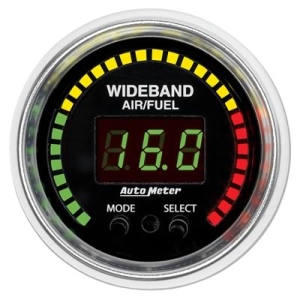 |
| Typical Air/Fuel ratio guage |
Probably the best approach is to get the jetting in the ballpark, then spend some time on ignition timing. Repeat the process to fine tune - you might have do it a couple of times. When you get it right you'll probably find that there is a range of a couple of jet sizes and a couple of degrees of advance where the performance barely changes. It's safest to be on the richer, less-advanced end of this range. If you're running a solid lifter cam you might also want to experiment with minor changes in valve clearances, and if you find significant gains from this it might indicate that a change in cam timing or a whole new cam would be beneficial. When you're tuning at the drag strip or with an in car timer concentrate mainly on the terminal speeds as these are an accurate indication of the engines output, whereas the ET is subject to variations in driving technique and how well you hook up off the line. You will find the terminal speeds surprisingly consistant, even if you stuff up the launch or gear changes etc. Not that I'd ever do that...
Earlier I mentioned that power output and fuel consumption are the two key indicators of engine efficiency. There are another couple of more subtle indicators you might want to keep an eye on too, and they are the jetting and timing requirements. Basically if the engine seems to want unusually rich jetting it's a sign of poor mixture quality and/or distribution, or perhaps overcarburation. Get that fixed and you'll find the engine will make more power and will want a smaller jet. Similarly, if the engine wants great gobs of spark advance at either end of the rev range then something isn't quite right, possibly not enough squish or a mismatch of compression ratio to cam timing. There is a difference though, between an efficient engine that makes peak power with moderate spark advance and one that can only tolerate so much advance before it rattles like a paint tin full of marbles..
Serving Suggestions
Here are a few recipes you might find interesting:The Poverty Pack
This is just a complete VK EFI 202 lifted from a Commodore. Often you can buy the whole car as cheaply as just the motor. When you've taken the motor out sell the wheels and some of the panels then leave it in the front yard as a conversation piece. Your missus will love it. Works well with LPG.
The Economy Pack This one is a cheap and civilised engine with good mileage and performance for a daily driver.
Black 202 block and head, perhaps with a little port cleanup work
9.5:1 compression
Mild cam - say 210 to 215 @ 0.050"
Standard manifold with Weber carb from an 3.3l XE Falcon and hi-capacity air filter (a quicker alternative would be a 390cfm Holley 4 barrel on a suitable manifold)
HEI ignition
Standard cast iron exhaust manifold with a single 2-1/2" system
The Old School Special (aka The Hoon) - A strong performing, sweet sounding nostalgia trip
Red 179, 173 or 186 block
3" crank, blue/black rods
10.5:1 compression
9 port Bathurst/YT style head, 1.7"/1.48" valves, maybe with a little additional port work
235 to 240deg @ 0.050" 0.45" lift solid lifter cam
Adjustable rockers
Triple 1.75" SUs or Strombergs CDs
HEI ignition
1.5" x 30" primary pipe extractors with 2-3/4" collector
A uteload of banjo diff centres and axles
The Early Model Sleeper - a sweet, legal 149 to replace the old grey..
149 block
3" crank
stock rods
Blue 173 head machined to get the compression up to 9.5:1, possibly with a light port cleanup
Stock 12 port intake with Weber carb from an 3.3l XE Falcon
HEI ignition
Mild cam - 205 to 210deg @ 0.050"
Stock 12 port cast exhaust manifold with a 2" single system
The Scream - 250hp+ (for a quicker revving variation on this one try a blue 173 block bored for 186 pistons and 3" crank)
Blue/Black 202 block
Blue/Black 3.25" crank
Blue/black rods
11:1 - 11.5:1 compression
Professionally ported 12 port head w 1.7" and 1.48" valves, or ported YellaTerra 12 port
Cleaned up manifold w/ triple 48mm Weber or Dellorto sidedrafts, alternatively triple 2" SU's
245 to 250deg @ 0.050" 0.48" to 0.5" lift solid cam
Shaft mount roller rockers
HEI or better ignition
1.625" x 28" primary pipe extractors with a single 3" x 15" collector
Links
A few links to suppliers and other sites of interest. Note that I don't have any business connections with any of these suppliers, and don't
necessarily use or endorse any of them in particular. Having said that, given enough coke and hookers I can be bribed to write all the right things....
Australian Specialty Racecraft make some very nice street and competition oil pans for the Holden six.
Sonic Injection are builders of very high quality EFI manifolds and throttle bodies, as well as main cap girdles and other parts.
Aussiespeed make and supply a wide variety of manifolds and other parts, and are now producing the Cullen Ultraflow
manifolds that are highly regarded by speedway racers.
PipeMax is an extremely useful software package, mainly for calculating header dimensions but has many other functions as well. Based on Blairs' proven formulae, it's very good value for money.
Engine Analyzer is just one of the racing-related software packages made by Performance Trends. It's an easy to use engine design program that lets you run theoretical dyno tests to compare different engine combinations.
Ignitech make ignition-only and ignition/injection controllers (ECUs). Originally designed for
bike engines but ideal for distributor-less Holden six competition engines as well.
J.Zed Heads are famous in the straight six world, and there is probably nothing that you can do
to a Holden six that will give the same performance increase. As well as heads, J.Zed can supply mechanical injection setups, manifolds and other Holden
six parts.
So there you have it, I hope you have found something useful here. If you have comments, corrections or suggestions I'd love to hear from you - send them to snarlyjohn@gmail.com. If there is enough interest in this page I might even pretty it up with some more pictures.. And as I said in the introduction, I don't pretend that it's 100% complete or accurate, but with your help we can get it close...
Johnno, 27/12/09

Building the Hot Holden Six by snarlyjohn@gmail.com is licensed under a Creative Commons Attribution-Noncommercial-Share Alike 2.5 Australia License.